In the next tutorial, we add a colored material and a light source to make our cube look a bit more interestingly and extend our logic processor to react on user key input. We will take the previous tutorial’s code as the basis for our next steps.
Find the project files in the folder tutorials/chapter01/02_color_cube/project.
Version 1: Structuring Graph Description Files
For reasons of clarity, we start by moving the definition of our cube’s material to a new file named graph_materials.xml. Splitting logical groups to multiple files is useful especially in larger projects and allows the easy reuse of existing components.
Namespaces
To avoid naming conflicts, it is possible to use Graph::Namespace nodes in our scene graph, which represent a way to hierarchically organize our graph nodes.
Similar to file paths in a computer file system, a named reference into the scene graph can be represented by a (nested) representation of namespace IDs, followed by the actual node ID. The / character serves as a separator, much like in an UNIX-like file system. A preceding / character denotes the root namespace analogous to an absolute file path. Without a preceding / , the referenced element can be specified relative to the current namespace. Moving up one level can be done using the character sequence ../ .
<MaterialState materialId="/material/mat_white">
<MaterialState materialId="../material/mat_white">
<MaterialState materialId="/material/uncolored/mat_white">
The above notation is used for referencing nodes within the loaded scene graph. Referencing individual resources from a loaded package works in a similar way. However, in this case it is necessary to specify the actual package by preceding its ID to the given resource ID. Here, the : character serves as separator:
<Instance graphResourceId="package_main:graph_mat"/>
In our example, the material’s path changes from "mat_white" to "/material/mat_white" when located in the "material" namespace, and "myCube01" changes to "/myGraph/myCube01" .
We also specify the optional attribute activeAndVisible="no" at the namespace node to deactivate and hide all nodes in its sub-tree. We will later see why.
<?xml version="1.0"?>
<Graph>
    <Namespace id="material" activeAndVisible="no">
        <FixedProgram
            id="prg_white"
        />
        <Material
            id="mat_white"
            programId="prg_white"
        />
    </Namespace>
</Graph>
We also change the file graph_main.xml to:
<?xml version="1.0" ?>
<Graph>
    <Instance graphResourceId="package_main:graph_mat"/>
    <Namespace id="myGraph">
        <View id="view"/>
        <Camera id="camera"
            viewId="view"
            fieldOfViewX="400"
            nearPlane="400" farPlane="2500"
            clearColorBuffer="1"
        >
            <CameraTransform
                cameraId="camera"
                posX="0" posY="0" posZ="800"
            />
            <MaterialState
                materialId="/material/mat_white"
                slot="0"
            />
            <CubeGeometry id="myCube01"
                scaleFactor="200"
                posX="0" posY="0" posZ="0"
            />
        </Camera>
    </Namespace>
</Graph>
Both resource files must be defined in the file package.xml in order to include them in the package:
<?xml version="1.0" ?>

<Package id="package_main">

  <!-- Graph resources -->
  <Resource id="graph_main" fileName="graph_main.xml"/>
  <Resource id="graph_mat" fileName="graph_materials.xml"/>

  <!-- Graph instances -->
  <Instance graphResourceId="graph_main"/>

</Package>
We can use the Graph::IRoot::PrintTree() method to print the whole sub-graph starting at a given node to the console. Comparing this output to the output of the previous example shows the actually created Namespace node: Additionally, it shows that the whole graph is embedded into a root namespace node.
<Namespace flags=e000011e vnode="2">
  <Container flags=e000011d vnode="1">
    <Instance flags=8000011e vnode="5">
      <Container flags=8000011e vnode="4">
        <Namespace id="material" flags=80000186 vnode="3">
          <FixedProgram id="prg_white" flags=0000001e vnode="1"/>
          <Material id="mat_white" flags=8000001e vnode="1"/>
        <Namespace/> <!-- id="material" -->
      <Container/>
    <Instance/>
    <Namespace id="myGraph" flags=e000011e vnode="6">
      <View id="view" flags=e000001e vnode="1"/>
      <Camera id="camera" flags=e000011e vnode="4">
        <CameraTransform flags=4000001e vnode="1"/>
        <MaterialState flags=8000001e vnode="1"/>
        <CubeGeometry id="myCube01" flags=8000001e vnode="1"/>
      <Camera/> <!-- id="camera" -->
    <Namespace/> <!-- id="myGraph" -->
  <Container/>
<Namespace/>
<Namespace flags=e000011e vnode="2">
  <Container flags=e000011d vnode="1">
    <View id="view" flags=e000001e vnode="1"/>
    <Camera id="camera" flags=e000011e vnode="6">
      <CameraTransform flags=4000001e vnode="1"/>
      <FixedProgram id="prg_white" flags=0000001e vnode="1"/>
      <Material id="mat_white" flags=8000001e vnode="1"/>
      <MaterialState flags=8000001e vnode="1"/>
      <CubeGeometry id="myCube01" flags=8000001e vnode="1"/>
    <Camera/> <!-- id="camera" -->
  <Container/>
<Namespace/>
When the root->PrintTree() method is called from OnInit(), it is possible that there are still some nodes remaining in the graph that actually belong to the startup package, even if UnloadPackage("startup") has already been called. The UnloadPackage() method simply puts the respective nodes in an inactive state and delegates the actual unloading process to a different thread. To receive a notification, when the package has been unloaded, the callback method OnPackageWasUnloaded() has to be overridden. There exist a total number of four callback methods for the purpose of signalling package loading states:
OnPackageWillBeLoaded(): called before load process startsOnPackageWasLoaded(): called after load process has finishedOnPackageWillBeUnloaded(): called before unload process startsOnPackageWasUnloaded(): called after unload process has finished
Version 2: Defining a Colored Material
In the next step, we define a new FixedProgram using the attribute value coloringEnabled="yes". In addition, we specify a material using default values, and a new FixedParameters node together with its diffuseColor attribute.
Depending on the format and suffix(es) given for that attribute, a color value can be specified in a number of different ways:
        <FixedProgram
            id="prg_color"
            coloringEnabled="yes"
        />
        <Material
            id="mat_color"
            programId="prg_color"
        />
        <FixedParameters
            id="par_cube_color"
            diffuseColor="0f, 0.50f, 0.75f, 1f"
        />
In the file graph_main.xml we now have to activate both our new material and parameter nodes for rendering. We could also safely omit the given attribute definition slot="0" as the default value for the slot attribute is 0 in any case.
            <CameraTransform
                cameraId="camera"
                posX="0" posY="0" posZ="800"
            />
            <MaterialState
                materialId="/material/mat_color"
                slot="0"
            />
            <ParametersState
                parametersId="/material/par_cube_color"
                slot="0"
            />
            <CubeGeometry id="myCube01"
                scaleFactor="200"
                posX="0" posY="0" posZ="0"
            />
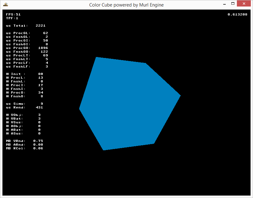
As a result, our cube gets rendered using the selected color:
Version 3: Defining a Light Source
To enable simple lighting for our cube, we have to perform two additional steps:
- Activate lighting for our given
FixedProgram - Create a light source in our scene graph.
Material lighting calculations can be simply enabled by using the lightingEnabled="yes" attribute:
        <FixedProgram
            id="prg_color"
            coloringEnabled="yes"
            lightingEnabled="yes"
        />
So far, we always added our cube as a child node of our camera to assign it to the camera for rendering. A generally more flexible way to perform this task is to use a CameraState node, which allows separating the definitions of camera and geometry. Analogous to material and parameters states, a CameraState node activates a camera for all subsequent rendering until a different CameraState node is encountered.
<?xml version="1.0" ?>

<Graph>
    <Instance graphResourceId="package_main:graph_mat"/>

    <Namespace id="myGraph">
        <View id="view"/>
        <Camera
            id="camera"
            viewId="view"
            fieldOfViewX="400"
            nearPlane="400" farPlane="2500"
            clearColorBuffer="1"
        />
        <CameraTransform
            cameraId="camera"
            posX="0" posY="0" posZ="800"
        />
        <CameraState
            cameraId="camera"
        />
In order to define a single light source object, we need another three graph nodes:
- An actual light source node (
Graph::Light) - A specialized transform node for positioning our light source (
Graph::LightTransform) - A state node to activate the light (
Graph::LightState)
The Light node is used to create an actual light source. The LightTransform node is used to position the light in our virtual world; in our case, we position it at the same position as out camera. The LightState node activates our light for all subsequent rendering operations:
        <Light
            id="light"
        />
        <LightTransform
            lightId="light"
            posX="0" posY="0" posZ="800"
        />
        <LightState
            lightId="light"
            unit="0"
        />
Now we can render our cube using a suitable material:
        <MaterialState materialId="/material/mat_color"/>
        <ParametersState parametersId="/material/par_cube_color"/>
        <CubeGeometry
            id="myCube01"
            scaleFactor="200"
            posX="0" posY="0" posZ="0"
        />
    </Namespace>
</Graph>
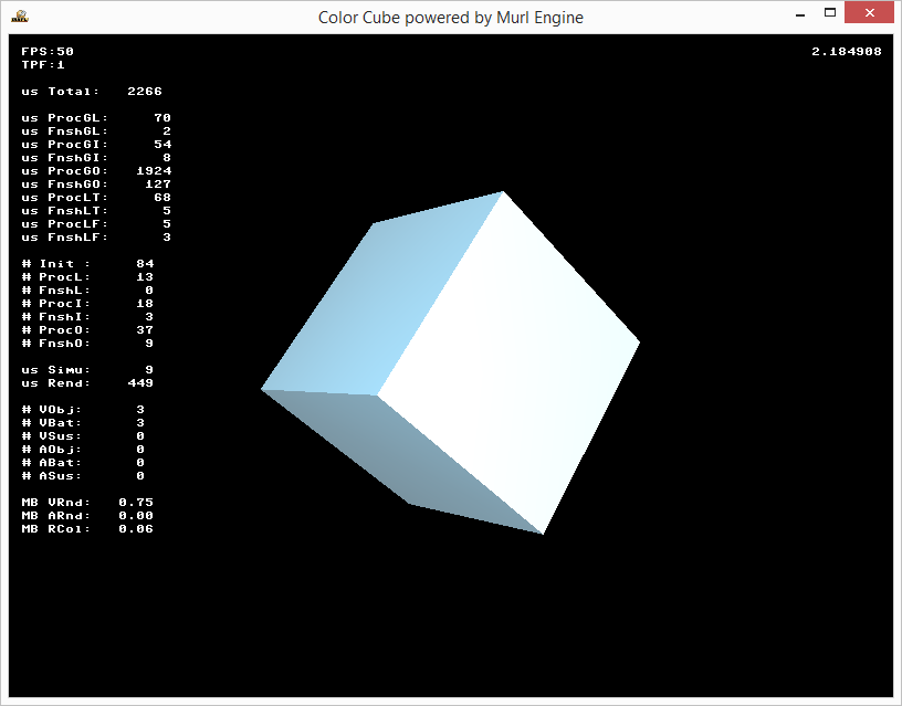
The result is a rotating cube with simple lighting enabled:
Version 4: Device Handler
To conclude this example, we want to be able to close our application, when the user presses the ESC key on a physical keyboard or the BACK button on an Android device, and furthermore, we also want to improve the color parameters for lighting.
To react on different user input, the Murl engine provides a device handler object (Logic::IDeviceHandler). We can obtain a pointer to this object using the Logic::IState::GetDeviceHandler() method. To check for physical keyboard input, we can use the device handler's WasRawKeyPressed() method; on Android buttons we can use WasRawButtonPressed().
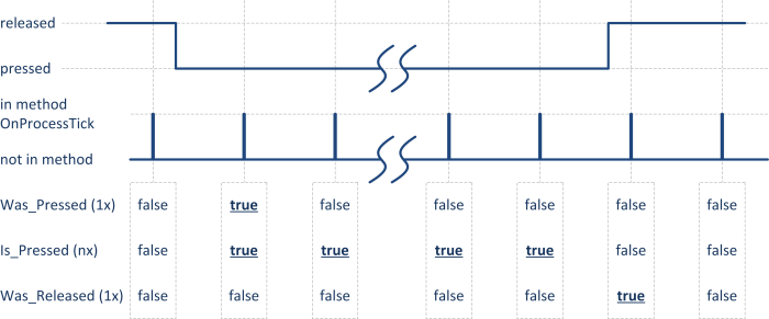
In addition to WasRawKeyPressed(), physical keyboard input is also reflected by the IsRawKeyPressed() and WasRawKeyReleased() methods. During a regular keystroke, these methods return true in the following sequence:
- At the moment of first pressing the key down,
WasRawKeyPressed()returnstruefor exactly one logic tick - As long as the key is down,
IsRawKeyPressed()returnstruein every logic tick. - When the key is released,
WasRawKeyReleased()returnstruefor exacly one logic tick.
This scheme (was pressed, is pressed, was released) can be found throughout the Murl engine, e.g. for Input::IRawKeyboardDevice, Input::IRawButtonDevice, Input::IJoystickDevice, Input::IMouseButtons etc.
void App::ColorCubeLogic::OnProcessTick(const Logic::IState* state)
{
    Double angle = state->GetCurrentTickTime();
    angle = Math::Fmod(angle, Math::TWO_PI);
    mCubeTransform->SetRotation(angle, angle, 0);
    state->SetUserDebugMessage(Util::DoubleToString(angle));

    Logic::IDeviceHandler* deviceHandler = state->GetDeviceHandler();
    if (deviceHandler->WasRawKeyPressed(RAWKEY_ESCAPE) ||
        deviceHandler->WasRawButtonPressed(RAWBUTTON_BACK))
    {
        deviceHandler->TerminateApp();
    }
}
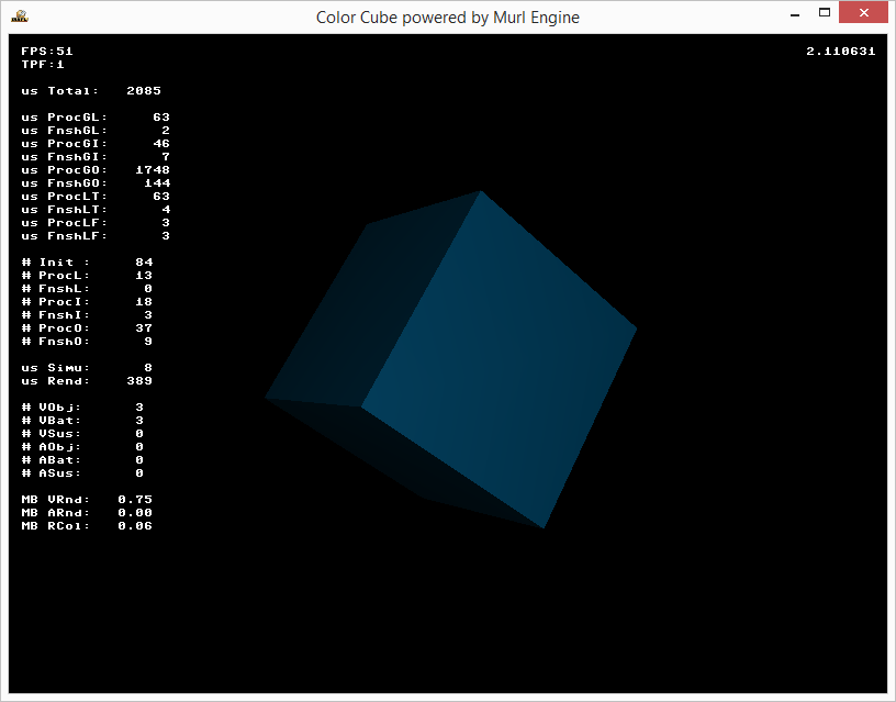
Finally, we can change the result of our cube’s lighting calculations by modifying the color values for both light source and parameter node for one or more of the individual components of the lighting equation:
        <Light
            id="light"
            diffuseColor="0.5f,0.5f,0.5f,1f"
        />
        <FixedProgram
            id="prg_color"
            coloringEnabled="yes"
            lightingEnabled="yes"
        />
        <Material
            id="mat_color"
            programId="prg_color"
        />
        <FixedParameters
            id="par_cube_color"
            diffuseColor="0f, 0.50f, 0.75f, 1f"
            specularColor="1f, 1f, 1f, 1f"
            ambientColor="0f, 0f, 0f, 1f"
            shininess="32"
        />
Exercises
- Try different color parameter values.
- What needs to be done to rotate the cube manually around the X, Y and Z axes using the keyboard keys 1, 2 and 3 respectively instead of automatic rotation?