In this tutorial, images are drawn using Graph::PlaneGeometry nodes with a two-dimensional texture applied. It has to be considered that the width and height of the texture have to be a number of the range 2^n (power of 2). Valid values are e.g. 1, 2, 4, 8, 16, 32, 64, 128, 256, 512, 1024, 2048 etc.
Version 1: Flat Texture
For our tutorial we create an image named gfx_smiley.png and save it in the sub-folder gfx . The image is specified in the file package.xml :
<Resource id="gfx_smiley" fileName="gfx/gfx_smiley.png"/>
In order to render the image, we need a suitable material with an activated texture unit. This material is created in the file graph_materials.xml. By using textureUnit0Enabled, the texture unit 0 is activated and blendMode="ALPHA" allows transparent sections to be drawn.
<?xml version="1.0"?>
<Graph>
    <Namespace id="material" activeAndVisible="no">

        <FixedProgram
            id="prg_color_texture"
            textureUnit0Enabled="yes"
        />

        <Material
            id="mat_alpha_color_texture"
            programId="prg_color_texture"
            visibleFaces="FRONT_AND_BACK"
            blendMode="ALPHA"
            depthBufferMode="NONE"
        />
Additionally, we create a Graph::FlatTexture node, which instantiates the image resource as graphic node. The attribute pixelFormat defines the format of the image in memory. It is possible that the pixel format in memory is different than the one stored in the resource file.
With the attribute useMipMaps it is possible to enable automatic mip-map generation. This means that a mip-map pyramid is created when loading the image. Enabling this attribute results in a higher loading time and 50% higher memory consumption. Usually, mip-mapping is not necessary for 2D applications, therefore, we disable it for our example.
        <FlatTexture
            id="texture_smiley"
            imageResourceId="package_main:gfx_smiley"
            pixelFormat="R8_G8_B8_A8"
            useMipMaps="no"
        />

    </Namespace>
</Graph>
In the file graph_main.xml we create an instance of these objects and activate them with MaterialState and TextureState.
<?xml version="1.0" ?>
<Graph>
<Instance graphResourceId="package_main:graph_mat"/>
<Instance graphResourceId="package_main:graph_camera"/>
<MaterialState materialId="material/mat_alpha_color_texture"/>
<TextureState textureId="material/texture_smiley"/>
<PlaneGeometry
id="plane"
scaleFactorX="128" scaleFactorY="128"
/>
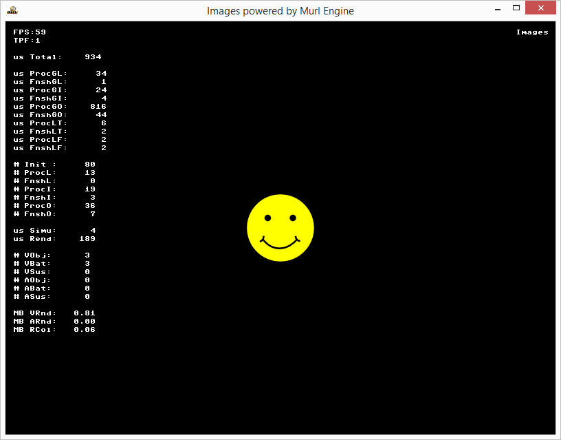
</Graph>
As a result, we receive a textured PlaneGeometry object:
Version 2: Position and Resize
The texture is always adjusted to the object. Depending on size and aspect ratio, the texture is scaled and/or deformed (see screenshot below).
By using the attributes texCoordX1, texCoordX2, texCoordY1 and texCoordY2 a section of the texture can be selected (see screenshot below).
    <PlaneGeometry
        id="plane7"
        scaleFactorX="64" scaleFactorY="128"
        texCoordX1="0.0" texCoordX2="0.5" texCoordY1="0.0" texCoordY2="1.0"
        posX="150" posY="0"
    />

    <PlaneGeometry
        id="plane8"
        scaleFactorX="128" scaleFactorY="64"
        texCoordX1="0.0" texCoordX2="1.0" texCoordY1="0.0" texCoordY2="0.5"
        posX="-150" posY="0"
    />
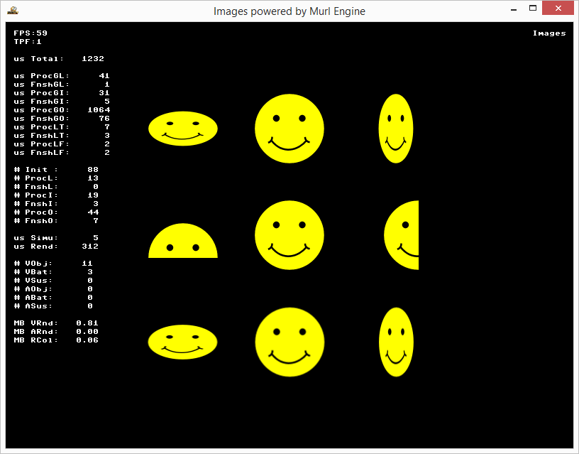
If the pixels of the texture graphic are exactly in between the pixel of the display surface after positioning the geometry object, the image appears blurry (see lowermost images in the screenshot above).
In order to avoid blurring, graphics always have to be placed on a whole-numbered position with an even-numbered pixel length. Graphics with an odd-numbered pixel length have to be placed in between two whole-numbered positions.
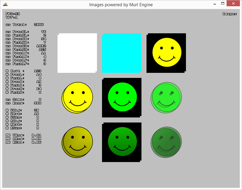
Version 3: Colored Texture
If coloringEnabled and textureUnit0Enabled are activated, the color is calculated by multiplying these two color parameters. This can e.g. be used for fade-in/fade-out effects (alpha channel) or to color textures.
        <FixedProgram
            id="prg_color_texture"
            textureUnit0Enabled="yes"
            coloringEnabled="yes"
        />
For a better illustration, we create various material nodes and draw two overlapping PlaneGeometry objects with each node. The parameters for camera, light, texture and color are identical for all objects. The order is analogous to the reading flow from left to right and from top to bottom.
        <FixedProgram
            id="prg_white"
        />
        <Material
            id="mat_white"
            programId="prg_white"
        />

        <FixedProgram
            id="prg_color"
            coloringEnabled="yes"
        />
        <Material
            id="mat_color"
            programId="prg_color"
        />
The first two objects are drawn with the materials mat_white and mat_color. Although a texture parameter has been set, it is not drawn as textureUnit0Enabled is deactivated.
        <FixedProgram
            id="prg_texture"
            textureUnit0Enabled="yes"
        />
        <Material
            id="mat_texture"
            programId="prg_texture"
            visibleFaces="FRONT_AND_BACK"
            blendMode="NONE"
            depthBufferMode="NONE"
        />
        <Material
            id="mat_alpha_texture"
            programId="prg_texture"
            visibleFaces="FRONT_AND_BACK"
            blendMode="ALPHA"
            depthBufferMode="NONE"
        />

        <FixedProgram
            id="prg_color_texture"
            textureUnit0Enabled="yes"
            coloringEnabled="yes"
        />
        <Material
            id="mat_color_texture"
            programId="prg_color_texture"
            visibleFaces="FRONT_AND_BACK"
            blendMode="NONE"
            depthBufferMode="NONE"
        />
        <Material
            id="mat_alpha_color_texture"
            programId="prg_color_texture"
            visibleFaces="FRONT_AND_BACK"
            blendMode="ALPHA"
            depthBufferMode="NONE"
        />
For the next four objects the texture unit 0 has been activated. The materials vary in their values for the attributes coloringEnabled and blendMode. Only if the blendMode is set to "ALPHA", the alpha channel (transparency) is considered while drawing. The color parameter has an alpha value of 0.5, which is why the fourth object has a transparency of 50%.
        <FixedProgram
            id="prg_texture_light"
            textureUnit0Enabled="yes"
            coloringEnabled="no"
            lightingEnabled="yes"
        />
        <Material
            id="mat_texture_light"
            programId="prg_texture_light"
            visibleFaces="FRONT_AND_BACK"
            blendMode="ALPHA"
            depthBufferMode="NONE"
        />

        <FixedProgram
            id="prg_color_texture_light"
            textureUnit0Enabled="yes"
            coloringEnabled="yes"
            lightingEnabled="yes"
        />
        <Material
            id="mat_color_light"
            programId="prg_color_texture_light"
            visibleFaces="FRONT_AND_BACK"
            blendMode="NONE"
            depthBufferMode="NONE"
        />
        <Material
            id="mat_alpha_color_texture_light"
            programId="prg_color_texture_light"
            visibleFaces="FRONT_AND_BACK"
            blendMode="ALPHA"
            depthBufferMode="NONE"
        />
The last three objects have their attribute lightingEnabled set to "yes". Therefore, a simple lighting effect can be achieved with a suitable light source.
- Note
- It is also necessary to set the attribute
hasNormalto"yes"for the illuminatedPlaneGeometryobjects. The calculation of the ligth intensity requires knowledge of the normal vectors for the respective geometry objects. Setting thehasNormalattribute causes the calculation of the normal vector for the correspondingPlaneGeometryobject.
  <MaterialState materialId="material/mat_texture_light"/>
  <PlaneGeometry id="plane6"
    hasNormal="yes"
    scaleFactorX="128" scaleFactorY="128"
    posX="-150" posY="-150"
  />
  <PlaneGeometry id="plane6a"
    hasNormal="yes"
    scaleFactorX="128" scaleFactorY="128"
    posX="-145" posY="-145" depthOrder="1"
  />