This next tutorial shows how to create a new package containing simple graph nodes, and how this package can be used in an application. The result will be a spinning cube on screen.
Like in the Hello World tutorial, the Cube tutorial projects are located in the folder tutorials/chapter01/01_cube/project, again with the different project files found in the respective sub-folders for each target platform.
Version 1: Basic Structure
We start by creating a simple application as shown in the previous tutorial (create/destroy functions, an app class, a logic class), and take this as a basis for our further work.
In the Configure() method we define the actual size of the display output (which directly affects the initial window size) by calling the SetDisplaySurfaceSize() method of the app configuration object, with a width of 800 pixels and a height of 600 pixels. In addition, we define a product name for our application by calling SetProductName():
Bool App::CubeApp::Configure(IEngineConfiguration* engineConfig, IFileInterface* fileInterface)
{
    IAppConfiguration* appConfig = engineConfig->GetAppConfiguration();

    engineConfig->SetProductName("Cube");
    appConfig->SetWindowTitle("cube powered by murl engine");
    appConfig->SetDisplaySurfaceSize(800, 600);
    appConfig->SetFullScreenEnabled(false);

    return true;
}
In the app’s Init() method, we add an if clause that evaluates the current build mode (Debug/Release) before adding the "debug" package, so that this package is only loaded when a debug build is made.
Additionally, we insert another two lines to load the "startup" and "main" packages and associate the "main" package with the logic class of our application. For now, we leave the latter statement commented out, until we have created the main package. (The "startup" package is provided with the tutorial in the data/v1/packages folder, it contains a simple animated loading screen).
Bool App::CubeApp::Init(const IAppState* appState)
{
    mLogic = new CubeLogic(appState->GetLogicFactory());
    ILoader* loader = appState->GetLoader();

    if (Util::IsDebugBuild())
    {
        loader->AddPackage("debug", ILoader::LOAD_MODE_STARTUP);
    }

    loader->AddPackage("startup", ILoader::LOAD_MODE_STARTUP);
    //loader->AddPackage("main", ILoader::LOAD_MODE_STARTUP);
    return true;
}
In the header file of our CubeLogic class, we do not only override the base class’ OnInit() method, but also the OnDeInit() and OnProcessTick() methods. The OnDeInit() method is called by the framework exactly once, immediately before the framework starts to unload the associated package (in our case, when the application is closed). The OnProcessTick() method is called repeatedly once per every logic step. In most cases, there will be exactly one logic step per frame with variable step duration. However, as already mentioned in the introduction section, this behavior can be changed through the IEngineConfiguration object.
        protected:
            virtual Bool OnInit(const Logic::IState* state);
            virtual Bool OnDeInit(const Logic::IState* state);
            virtual void OnProcessTick(const Logic::IState* state);
The first thing we do in the OnInit() method is unload the startup package. The only purpose of the startup package is to give visual feedback (i.e. a "loading" screen) during loading the rest of the packages. After this is finished, the startup package is no longer needed and can be unloaded. The OnProcessTick() method remains empty for now and the OnDeInit() method simply returns true.
Bool App::CubeLogic::OnInit(const Logic::IState* state)
{
    state->GetLoader()->UnloadPackage("startup");

    if (!AreGraphNodesValid())
    {
        return false;
    }

    state->SetUserDebugMessage("Cube Init succeeded!");
    return true;
}

Bool App::CubeLogic::OnDeInit(const Logic::IState* state)
{
    return true;
}

void App::CubeLogic::OnProcessTick(const Logic::IState* state)
{
}
The result is a black window showing a loading screen and debug information.
Exercises
- Why is the user debug message
"Cube Init succeeded!"not shown? - What happens, if we associate the logic instance with the main package instead of the startup package? Why?
- What happens, when we try to load the main package?
Version 2: Creating a Package
In the next step, we create the still missing main resource package. We first create a sub-folder in the already existing data/v2/packages folder (which already contains the startup.murlpkg file) with the desired name and suffix .murlres:
data/v2/packages/main.murlres
Every "murlres" package needs at least one file with the exact name package.xml, which describes the actual contents of the package. In addition, we need another file that contains a description of the scene graph we want to create. We are free to choose any name for this file. In our case, we call it graph_main.xml.
data/v2/packages/main.murlres/package.xmldata/v2/packages/main.murlres/graph_main.xml
Both files contain valid XML contents and start with the XML declaration <?xml version="1.0" ?>.
The file package.xml defines, which resources are included in the package and which (sub-)graph instances should automatically be created, when the package is loaded. The file starts with the Package root element, which defines an id attribute. This root element identifies the document as a Package Resource Document. The id attribute is used to specify a unique name for that package, which will be later used to reference individual resources inside the package.
- Note
- Caution! Package id attributes always have to be unique!
Inside the root element we define two child elements. The text inside the <!-- and --> markers is treated as simple comment and has no further meaning.
The Resource child element introduces the file graph_main.xml as a resource within the package and assigns a unique name. The Instance child element is used to create an instance for this resource, when the package is loaded pointing at our (only) graph resource with the previously defined ID graph_main.
<?xml version="1.0" ?>

<Package id="package_main">

    <!-- Graph resources -->
    <Resource id="graph_main" fileName="graph_main.xml"/>

    <!-- Graph instances -->
    <Instance graphResourceId="graph_main"/>

</Package>
The file graph_main.xml contains a description of the individual graph nodes we want to create – in other words the scene we want to load.
The Graph element represents the root element of the file and identifies the file as a Graph Resource Document. Within the root element the individual graph nodes making up the actual graph are defined. A list of possible nodes can be found in the subfolder base/include/engine/graph.
<?xml version="1.0" ?>

<Graph>
To define our actual scene, we need to perform the following steps:
- Create a view to define the drawing area on screen
- Define a camera to specify the visible area of our virtual world
- Create a material to describe the appearance of a drawable object
- Select the material for rendering subsequent scene geometry
- Define the actual geometry objects to render
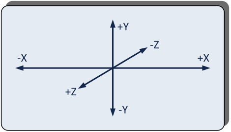
All geometry objects in the virtual world are positioned within a right-handed three-dimensional Cartesian coordinate system. The following illustration shows this coordinate system, with the origin at the center, the X axis running horizontally from left to right, the Y axis vertically from bottom to top, and the Z axis towards the viewer (back to front).
A graph may contain one or more Graph::View nodes and one or more camera nodes (Graph::Camera). Each of these views may contain any number of cameras, but each camera can have only one view assigned. While a view node is responsible for defining the rendering area within the output window, a camera node defines the actually visible part of the virtual world, which is then displayed within the view area. By default, the view area fills up the whole window.
We first create such a default View node and assign it the unique ID "view". Afterwards, we create a Camera that performs a perspective projection of our world to the screen with the given ID "camera" and create a connection to our previously created view node by specifying the view’s ID in the viewId attribute of the camera.
To define which geometry should be rendered using this camera, we first have to activate the camera by using a Graph::CameraState node. Alternatively, as in this example, the relevant geometry can also be defined between start tag and end tag within the camera’s sub-graph. In this case, the camera is only active for nodes within that sub-graph.
Using a Graph::CameraTransform node and its attributes posX , posY and posZ, we are able to specify the camera’s position within our virtual world. To rotate the camera, the attributes axisX , axisY, axisZ and angle can be used. By default, the camera is placed at the coordinate origin (0/0/0) looking along the negative Z axis towards negative infinity.
    <View id="view"/>

    <Camera
        id="camera"
        viewId="view"
        fieldOfViewX="400"
        nearPlane="400" farPlane="2500"
        clearColorBuffer="true"
    >

        <CameraTransform
            cameraId="camera"
            posX="0" posY="0" posZ="800"
        />
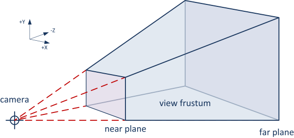
The camera attributes nearPlane and farPlane define the absolute distances of the near and far clipping planes of the camera. The fieldOfViewX attribute specifies the width of the near plane in X direction. The combination of these attributes defines the actual viewing area of the camera. The resulting volume has the form of a pyramid with its tip cut off, also known as a frustum. All geometry lying within that viewing frustum will be rendered to the view by performing a perspective projection onto the near plane.
As we did not explicitly specify any value for the fieldOfViewY attribute, the actual height of the near plane (the size of the viewing frustum in Y direction) is calculated by the framework to maintain a square coordinate aspect ratio (1.0) between X and Y coordinates.
Instead of only specifying fieldOfViewX, we could also only specify fieldOfViewY to set the vertical size. In this case, the horizontal size will be recalculated.
If both attributes (fieldOfViewX and fieldOfViewY) are given at the same time, both the horizontal and vertical sizes are set to a fixed value. In that case, if the window aspect ratio is changed during resizing, the result will be a distorted image with a non-square coordinate aspect ratio.
We also specify the attribute clearColorBuffer="true" to make sure that the window contents are cleared during each frame prior to rendering the actual scene.
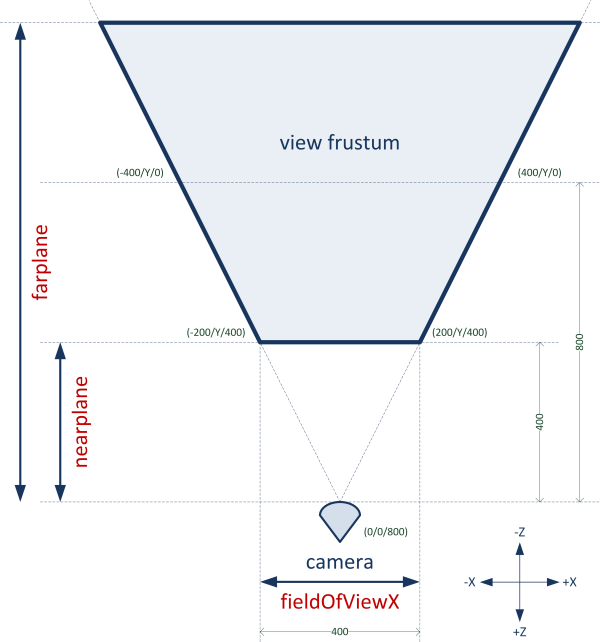
Actually, the values chosen for our camera parameters are no coincidence. In the resulting frustum, the "window" to our virtual world coordinates at Z=0 is exactly twice as wide and high as at the near plane (Z=400), which results in a width of 800 coordinate units at Z=0. Together with our actual window width of 800 pixels, this results in a 1:1 mapping of pixels to virtual coordinates in the Z=0 plane.
This is especially useful in 2D applications as moving an object, that is positioned in the Z=0 plane, by one coordinate unit results in a movement of exactly one pixel in the output window. If the same object was positioned within the near plane, moving it by one coordinate unit would result in a two pixel movement.
In order to correctly render any object, it has to be positioned within the camera’s defined frustum. Special care has to be taken when positioning "flat" objects (e.g. Graph::PlaneGeometry nodes), which should not be placed too close to either the near or far planes. Due to graphics hardware inaccuracies it might happen that such an object starts to flicker or completely disappear.
In the next step, we define a material we want to use for rendering our cube. A material basically consists of:
- A program node defining the way how output pixels are colored
- A material node and
- An optional parameters node controlling various properties like color etc.
The program can either be a predefined one resembling the fixed-function pipeline of older GPUs (Graph::FixedProgram) or a user-definable Graph::ShaderProgram, which directly accepts GPU shader language source code to perform highly customized GPU rendering. For simplicity reasons, we start with a simple FixedProgram using default values and only define its id attribute so that it can be referenced:
        <FixedProgram
            id="prg_white"
        />
The material itself defines a set of attributes that are independent from the actual shader program. We define a Graph::Material node, using default values again and an id attribute. Additionally, we must tell the material which program to use, which can be done by specifying the programId attribute:
        <Material
            id="mat_white"
            programId="prg_white"
        />
In the next step, we "activate" the material for rendering, using a Graph::MaterialState node. By specifying the materialId attribute we select the actual material and assign it to one of 128 possible material slots. In our case, all subsequent geometry referring to material slot 0 for rendering (the default) will now be rendered using the material "mat_white":
        <MaterialState
            materialId="mat_white"
            slot="0"
        />
To complete our first scene graph, we now have to create our actual cube for rendering. We assign it the unique ID "myCube01", its center is defined by setting the posX , posY and posZ attributes to the coordinate (0/0/0), and we set the cube’s X, Y and Z dimensions to 200 units (in fact, the Graph::CubeGeometry node by default creates a unit cube and we simply scale it to our desired size).
        <CubeGeometry
            id="myCube01"
            scaleFactor="200"
            posX="0" posY="0" posZ="0"
        />

    </Camera>

</Graph>
The order, in which graph nodes are defined, is important for two reasons:
- A node can only make reference to another node, when the other node is already defined (top-down). In other words, e.g. a
MaterialStatecannot be connected to aMaterialthat is defined "further down" in the XML file or in another XML file that is loaded later. - State nodes like
CameraState,MaterialStateorParametersStatechange the traversal context and affect all subsequent nodes.
Loading the Package
The only step left to complete the first real version of the cube tutorial is the removal of the comment characters at the beginning of the loader->AddPackage("main", ...) line in the file cube_app.cpp, in order to load our newly created resource package from our application:
Bool App::CubeApp::Init(const IAppState* appState)
{
    mLogic = new CubeLogic(appState->GetLogicFactory());
    ILoader* loader = appState->GetLoader();

    if (Util::IsDebugBuild())
    {
        loader->AddPackage("debug", ILoader::LOAD_MODE_STARTUP);
    }

    loader->AddPackage("startup", ILoader::LOAD_MODE_STARTUP);
    loader->AddPackage("main", ILoader::LOAD_MODE_BACKGROUND, mLogic->GetProcessor());
    return true;
}
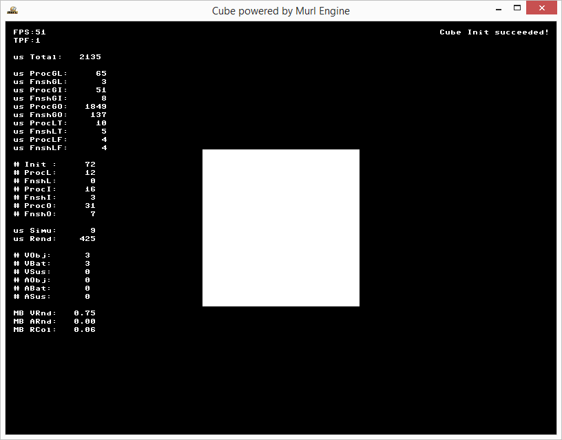
The result is a static, white cube in the middle of our window. As we are directly looking at its front face, we only see a white square:
If we take a closer look at the two lines responsible for loading the startup package and the main package, we notice that those two lines use a different LoadMode.
Load Modes
Loading a package can be done using one of the following three different modes:
The LOAD_MODE_STARTUP mode is used to quickly display a start-up logo or a loading screen. Packages using this mode are loaded even before the framework’s actual rendering loop is started. Until these packages are loaded, the screen/window remains black.
Packages using LOAD_MODE_BACKGROUND are loaded asynchronously in parallel to the framework’s rendering loop. Packages already loaded with LOAD_MODE_STARTUP are already displayed during this phase. After the background loading of a package is finished, any possible graph instances from this package are created. If a logic processor was associated with that package, that processor’s OnInit() method is called.
Packages using LOAD_MODE_ON_DEMAND are not automatically loaded, but registered by AddPackage() for later use. Loading and unloading of such packages can be performed on demand using the LoadPackage() and UnloadPackage() methods of the ILoader interface. The ILoader object, which was used to actually register the package during OnInit(), can later be referenced from within an OnProcessTick() method via the IState object parameter:
state->GetLoader()->LoadPackage("demand_package");
state->GetLoader()->UnloadPackage("demand_package");
The individual packages are sequentially loaded in the given order. Therefore, for a logic processor associated with a given package it is ensured, that this package and all previous ones are fully loaded before the OnInit() method is called.
As a general rule, the LOAD_MODE_STARTUP should only be used for small packages that can be quickly loaded, for the purpose of e.g. a start-up display. All other packages should be loaded using one of the other two modes. Therefore, the debug and startup packages are usually loaded using LOAD_MODE_STARTUP, and all subsequent autoload packages using LOAD_MODE_BACKGROUND, with the last one being associated with the main logic processor.
Resource Packer
Another difference between the startup and main packages is the actual package format on disk.
The main package is represented by a folder with the name main.murlres, which contains a package description file and individual resource files.
The startup package is represented by a single file with the name startup.murlpkg, which is essentially a binary representation of a .murlres folder, with all the necessary individual resource files packed into one single file.
The resource_packer tool can be used to convert a .murlres resource folder to such a binary package. The easiest way to use this tool is using the Dashboard. The menu command Project → Resource Packer Build creates exactly one binary .murlpkg file from each individual .murlres folder present in the data/packages folder.
Alternatively, the resource_packer command line tool can be used directly. Depending on the host platform, the executable can be found in different locations:
murl/base/binaries/win32/vs2008/Release/resource_packer.exemurl/base/binaries/win32/vs2010/Release/resource_packer.exemurl/base/binaries/osx/Release/resource_packer
During development, it is advantageous to work with a resource folder instead of binary packages as every change to any of the package’s resource files is automatically visible, when the developed application is started the next time, and the intermediate packing step is not necessary.
When doing a release build, however, binary packages are the better alternative. Binary packages are usually smaller, can be loaded much quicker, and it is much easier to include them into an application binary package.
By default, on all platforms except Android, the debug build of an application implicitly tries to load a package from a .murlres folder first if no explicit package suffix is given. Release builds on the other hand, and also debug builds on Android, prefer .murlpkg files over .murlres folders.
To override this behavior, it is possible to specify either the .murlpkg or .murlres suffix for a package, which forces the loader to only accept a package of that type:
// Load Resource Directory
loader->AddPackage("main.murlres", ILoader::LOAD_MODE_BACKGROUND);

// Load Binary Package
loader->AddPackage("main.murlpkg", ILoader::LOAD_MODE_BACKGROUND);

// Load what is preferred in the current build mode
loader->AddPackage("main", ILoader::LOAD_MODE_BACKGROUND);
As an alternative, it is possible to globally change the preferred package type by calling the IEngineConfiguration object's SetPreferredResourcePackageType() method.
- Note
- Hint! The method
SetResourceFileCategory()can be used to change the working directory of the package loader. By default, on desktop platforms the package loader is searching in the current directory in debug mode and in the application ressource bundle in release mode. With e.g.engineConfig->SetResourceFileCategory(IEnums::FILE_CATEGORY_CURRENT)the package loader would always search in the current directory.
Exercises
- How has the cube’s position to be changed that the cube’s right edge is aligned with the right window border?
- How has the cube’s size and position to be changed that the cube makes up an area of 600x600 pixels in the window?
- Try to change the window’s size and aspect ratio. What happens to the output?
- What happens to the output, when you add the
fieldOfViewY="400"attribute to the camera node?
Version 3: Transform Node
In the next step, we want to add an automatic rotation to the cube. For this purpose, we must obtain a reference to the cube node in the scene graph and continuously increase its rotation angle during each logic step.
The files murl_logic_graph_node_types.h and murl_logic_graph_node.h contain a number of suitable class declarations that serve the purpose of querying and manipulating different types of graph nodes:
murl/base/include/engine/logic/murl_logic_graph_node.hmurl/base/include/engine/logic/murl_logic_graph_node_types.h
Among these, one class suitable for rotating our cube is Logic::TransformNode. This class can be used to transform any graph nodes that implement the Graph::ITransform interface, which is the case for our CubeGeometry. We declare the new mCubeTransform member variable inside our CubeLogic class of the type TransformNode
        class CubeLogic : public Logic::BaseProcessor
        {
        public:
            CubeLogic(Logic::IFactory* factory);
            virtual ~CubeLogic();

        protected:
            virtual Bool OnInit(const Logic::IState* state);
            virtual Bool OnDeInit(const Logic::IState* state);
            virtual void OnProcessTick(const Logic::IState* state);

            Murl::Logic::TransformNode mCubeTransform;
        };
As a next step, we need to "connect" our mCubeTransform member variable to the actual cube node, which is present in the scene graph after loading our main package. The best way to do so is to use the OnInit() method of our logic processor. The GetGraphRoot() method of the given Logic::IState object can be used to gain access to the scene graph’s root object. This object always exists – even if the scene graph is completely empty.
The method mCubeTransform.GetReference() starts at the given graph root and recursively searches the scene graph for a node with the given id. If found, a reference to the respective node is stored in our mCubeTransform object.
The return value of this method is a pointer to a Logic::IObservableNode object. As long as there is an active reference to a specific graph node, it has to be assured that this graph node does not get removed from the scene graph by e.g. a call to UnloadPackage(). Otherwise it could happen that a logic processor still accesses the interface of a "dead" node, which most likely results in an undefined behavior or even a crash of the application.
For that reason, the Murl engine implements a simple safety mechanism that helps to detect such situations: The framework generates an error output in the console, if the application tries to remove a graph node that is still referenced at least once. Therefore, it is mandatory to manually release all graph node references, when they are no longer needed (in the destructor, at the latest), by a call to RemoveReference():
// Get Reference for mCubeTransform
Logic::IObservableNode* observableNode = mCubeTransform.GetReference(root, "myCube01");

// Remove Reference
observableNode->RemoveReference();
// alternatively
mCubeTransform.RemoveReference();
In order to manage references in a more comfortable way, the BaseProcessor class offers the convenient method AddGraphNode(). This method keeps track of all requested references and passes the responsibility of removing references on to the BaseProcessor itself. All tracked references are released automatically, when the BaseProcessor's destructor is called.
Bool App::CubeLogic::OnInit(const Logic::IState* state)
{
    state->GetLoader()->UnloadPackage("startup");

    Graph::IRoot* root = state->GetGraphRoot();
    AddGraphNode(mCubeTransform.GetReference(root, "myCube01"));

    if (!AreGraphNodesValid())
    {
        return false;
    }

    state->SetUserDebugMessage("Cube Init succeeded!");
    return true;
}
After storing a reference to our cube node in mCubeTransform, we can start to rotate the cube. We do this in the OnProcessTick() method, where we use the SetRotation() method of the Graph::ITransform interface. We calculate a rotation angle which is simply based on the current tick time, commonly used for both the X and Y axes. (Even though it is not necessary, we restrict the calculated angle value to the range from 0 – 2*π through the use of the Math::Fmod() function).
As an extra feature, we display the current angle value in the upper right window corner using the already known SetUserDebugMessage() function. For this purpose, we must first convert the Double variable to a String using the Util::DoubleToString() function:
void App::CubeLogic::OnProcessTick(const Logic::IState* state)
{
    Double angle = state->GetCurrentTickTime();
    angle = Math::Fmod(angle, Math::TWO_PI);
    mCubeTransform->SetRotation(angle, angle, 0);
    state->SetUserDebugMessage(Util::DoubleToString(angle));
}
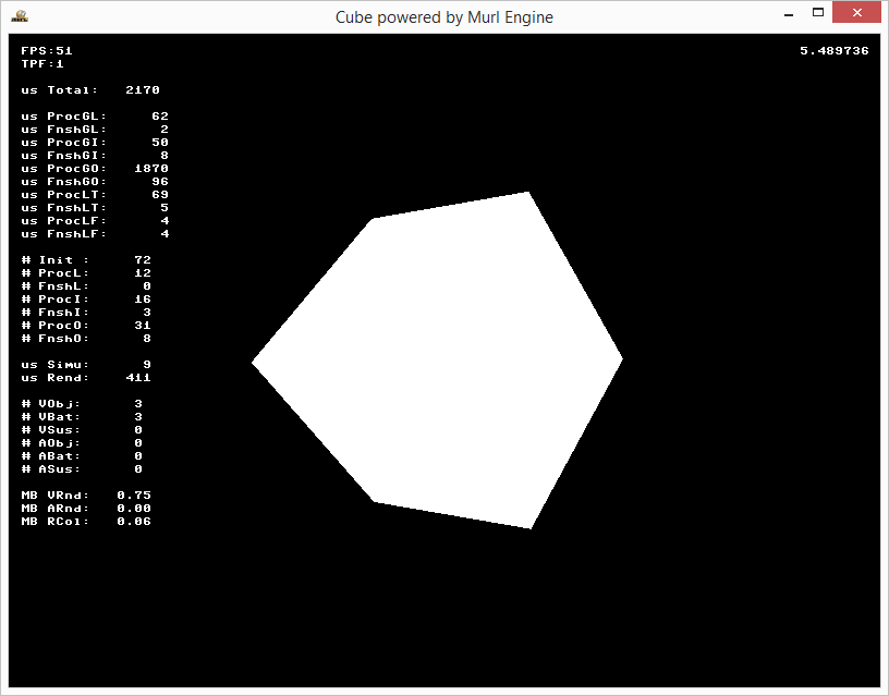
As a result, we see a spinning white cube: