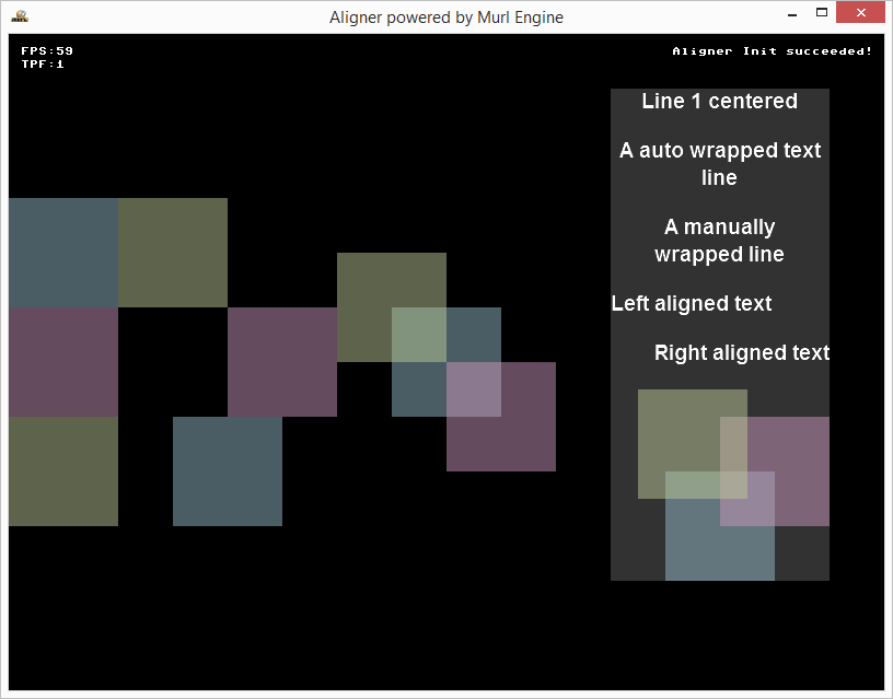
This tutorial describes how to automatically align objects utilizing the Graph::Aligner node.
ContainerAlignment
Independently from the Aligner graph node, several graph nodes (e.g. PlaneGeometry or TextGeometry) allow the adjustment of their anchor point via the containerAlignmentX and containerAlignmentY attributes. By default the anchor point is in the center.
Valid values are listed in the enums IEnums::AlignmentX and IEnums::AlignmentY:
UNDEFINEDLEFT(orBOTTOMfor Y)CENTER(default)RIGHT(orTOPfor Y)NEGATIVEPOSITIVE
As an example we place three planes on the same position 0/0/0 and change merely the parameter containerAlignmentX and containerAlignmentY (as well as the color parameter).
<!-- blue plane -->
<PlaneGeometry id="box_plane_01"
               posX="0" posY="0" scaleFactor="100"
               parametersSlot="0" materialSlot="2"/>
<!-- red plane -->
<PlaneGeometry id="box_plane_02"
               posX="0" posY="0" scaleFactor="100"
               parametersSlot="1" materialSlot="2"
               containerAlignmentX="LEFT" containerAlignmentY="TOP"/>
<!-- green plane -->
<PlaneGeometry id="box_plane_03"
               posX="0" posY="0" scaleFactor="100"
               parametersSlot="2" materialSlot="2"
               containerAlignmentX="RIGHT" containerAlignmentY="BOTTOM"/>
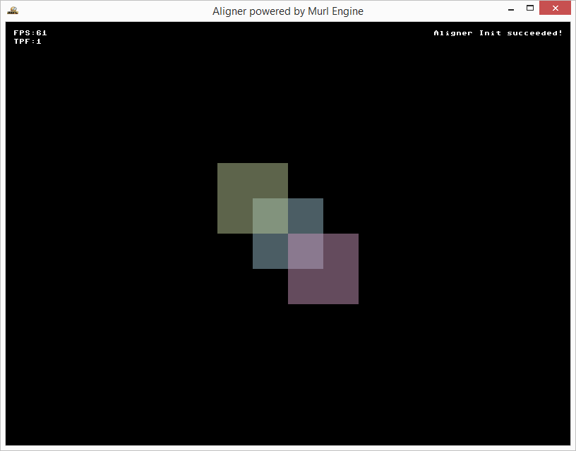
As result we get three planes which are differently positioned according to their alignment specification. The anchor world position is the same for all three planes (0/0/0) but the anchor point on the planes differ. For the blue plane the anchor point is in the center, for the red plane it is top left and for the green plane it is bottom right.
Aligner Graph Node
The Aligner graph node allows to automatically arrange objects along one dedicated main axis. The Aligner node calculates the bounding box of its child nodes (or sub graphs) and arranges them consecutively. As a first example let us arrange three PlaneGeometry objects along the Y axis.
<Aligner id="aligner01"
         axis="Y" posX="-200" >
    <!-- blue plane -->
    <PlaneGeometry scaleFactor="100" parametersSlot="0" materialSlot="2"/>
    <!-- red plane -->
    <PlaneGeometry scaleFactor="100" parametersSlot="1" materialSlot="2"
                   containerAlignmentX="LEFT" containerAlignmentY="TOP"/>
    <!-- green plane -->
    <PlaneGeometry scaleFactor="100" parametersSlot="2" materialSlot="2"
                   containerAlignmentX="RIGHT" containerAlignmentY="BOTTOM"/>
</Aligner>
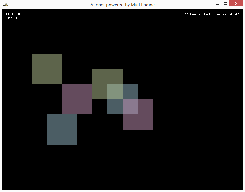
We move the center of the Aligner node to the left at position -200/0/0. The PlaneGeometry objects will be arranged along the Y axis automatically. The other coordinate values (X/Z) remain unchanged.
The attribute objectAlignment can be used to also adjust the other coordinate values (in our case X and Z). For example, specifying the parameter objectAlignmentX="LEFT" causes an object alignment along the left margin.
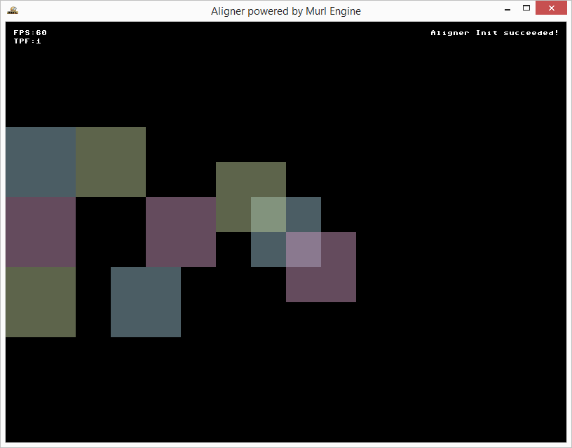
To illustrate that feature, we create a new Aligner node and specify the objectAlignmentX attribute. By specifying posY="150" and containerAlignmentY="TOP" the upper boundary of the Aligner node is placed to position 150. The parameter order="DESCENDING" causes a descending order.
<Aligner id="aligner02"
     axis="Y"  posX="-350" posY="150" containerAlignmentY="TOP"
     objectAlignmentX="LEFT"
     order="DESCENDING">
    <!-- blue plane -->
    <PlaneGeometry scaleFactor="100" parametersSlot="0" materialSlot="2"/>
    <!-- red plane -->
    <PlaneGeometry scaleFactor="100" parametersSlot="1" materialSlot="2"
                   containerAlignmentX="LEFT" containerAlignmentY="TOP"/>
    <!-- green plane -->
    <PlaneGeometry scaleFactor="100" parametersSlot="2" materialSlot="2"
                   containerAlignmentX="RIGHT" containerAlignmentY="BOTTOM"/>
</Aligner>
The attribute spacing can be used to define a distance between the aligned object and the attribute padding defines an outer border for the Aligner node.
<Aligner id="aligner03"
axis="Y" posX="250" posY="250" containerAlignmentY="TOP"
containerSizeX="200" order="DESCENDING" spacing="20">
<TextGeometry
materialSlot="4" systemFontName="SansBold"
fontSize="20"
textColor="255i, 255i, 255i, 255i"
backgroundColor="0i, 0i, 0i, 0i"
text="Line 1 centered"
enableWordWrapping="yes"
containerSizeX="200"
textAlignmentX="CENTER"
/>
<TextGeometry
materialSlot="4" systemFontName="SansBold"
fontSize="20"
textColor="255i, 255i, 255i, 255i"
backgroundColor="0i, 0i, 0i, 0i"
text="A auto wrapped text line"
enableWordWrapping="yes"
containerSizeX="200"
textAlignmentX="CENTER"
/>
<TextGeometry
materialSlot="4" systemFontName="SansBold"
fontSize="20"
textColor="255i, 255i, 255i, 255i"
backgroundColor="0i, 0i, 0i, 0i"
text="A manually wrapped line"
enableWordWrapping="yes"
containerSizeX="200"
textAlignmentX="CENTER"
/>
<TextGeometry
materialSlot="4" systemFontName="SansBold"
fontSize="20"
textColor="255i, 255i, 255i, 255i"
backgroundColor="0i, 0i, 0i, 0i"
text="Left aligned text"
enableWordWrapping="yes"
containerSizeX="200"
textAlignmentX="LEFT"
/>
<TextGeometry
materialSlot="4" systemFontName="SansBold"
fontSize="20"
textColor="255i, 255i, 255i, 255i"
backgroundColor="0i, 0i, 0i, 0i"
text="Right aligned text"
enableWordWrapping="yes"
containerSizeX="200"
textAlignmentX="RIGHT"
/>
<Node>
<PlaneGeometry scaleFactor="100" parametersSlot="0" materialSlot="2" containerAlignmentY="TOP"/>
<PlaneGeometry scaleFactor="100" parametersSlot="1" materialSlot="2"
containerAlignmentX="LEFT" />
<PlaneGeometry posX="25" posY="-25" scaleFactor="100" parametersSlot="2" materialSlot="2"
containerAlignmentX="RIGHT" containerAlignmentY="BOTTOM"/>
</Node>
</Aligner>
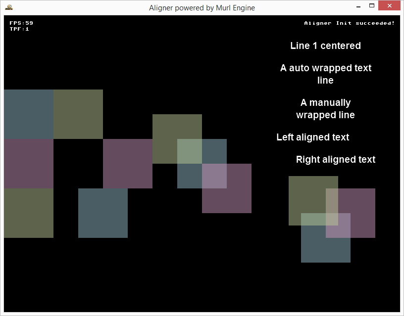
The final size of the Aligner can be queried with the method GetBoundingVolume(). The request should be done in the OnFinishTick() method and not in the OnProcessTick() method because the automatic alignment of the Aligner objects is performed after the method OnProcessTick() has been executed. Hence a request in the OnProcessTick() method would return the values of the previous frame.
void App::AlignerLogic::OnFinishTick(const Logic::IState* state)
{
    // Size
    if (mPrintBoundingValues)
    {
        const Graph::IBoundingVolume* boundingVolume = mAligner->GetBoundingVolume();
        const Graph::Box& box = boundingVolume->GetInnerLocalBox();
        const Graph::Vector& min = box.GetMinimum();
        const Graph::Vector& max = box.GetMaximum();
        Debug::Trace("From OnFinishTick:");
        Debug::Trace("  Bounding X %f / %f", min.x, max.x);
        Debug::Trace("  Bounding Y %f / %f", min.y, max.y);
        Debug::Trace("  Bounding Z %f / %f", min.z, max.z);
        mPrintBoundingValues = false;
    }
}
The result for the Aligner aligner03 and the first frame is:
For all further frames the call in the method OnProcessTick() and the call in the method OnFinishTick() return the same values. This is because the child nodes of the Aligner do not change and therefore the IBoundingVolume stays the same. The IBoundingVolume for another frame can be printed out by pressing the key P:
We can optically verify the calculated IBoundingVolume with a PlaneGeometry node:
<PlaneGeometry posX="250" posY="250" containerAlignmentY="TOP"
                scaleFactorX="200" scaleFactorY="450"
                parametersSlot="3" materialSlot="2" depthOrder="-1" />
