Visible surface determination is usually done with the Z-buffer technique (also known as depth buffering). In this case the drawing order of the objects is irrelevant for the render result. However, the Z-buffer technique only works with opaque faces but not with transparent faces. Transparent, overlapping faces have to be drawn in the correct order sorted from back to front. This is because the drawing order has a significant impact to the final compound color.(1)
Thus it is often wise to render the opaque geometries at first with Z-buffering enabled and the transparent geometries afterwards accessing the Z-buffer in read-only mode. Also for overlays, HUDs and various effects the render order often plays a vital role.
This tutorial describes the exact sequence in which the rendering occurs and shows ways to control the render order.
- Note
- (1) Also other techniques exist which allow to draw transparent faces order independent - e.g. Weighted Blended Order-Independent Transparency.
Render Hierarchy
The drawing order of the renderer can be controlled in several hierarchy levels:
- Framebuffer/Backbuffer
- View
- Camera
- Layer
- Pass
- SortOrder/Distance/DepthOrder
Framebuffer/Backbuffer
At first all Framebuffers are rendered in the order in which they are defined in the scene graph. At last the back buffer is rendered.
View
For each frame buffer / back buffer one or more Graph::View objects can exist.
A view specifies a display window or a region in the window (integer coordinates, pixels). The view has always the same size as the corresponding frame buffer / back buffer. A view mask can be used to restrict the drawing area to a smaller, rectangular region ("scissor test").
The render order can be defined with the attribute depthOrder. If the depthOrder value is the same for two views, the order in the scene graph defines the actual render order. A higher depthOrder value results in the view being rendered later, i.e. on top of all other views in the same frame buffer with lower depthOrder values.
Camera
For each view one or more Graph::Camera objects can exist
A Graph::Camera object specifies a visible area within the virtual world (floating point coordinates).
The render order can be defined with the attribute depthOrder. If the depthOrder value is the same for two cameras, the order in the scene graph defines the actual render order. A higher depthOrder value results in the camera being rendered later, i.e. on top of all other cameras within the same view with lower depthOrder values.
Layer
Each camera renders its objects (assigned by child nodes or with the Graph::CameraState node).
The rendering can be split up into several layers. By default, all geometries are rendered to layer 0. A Graph::LayerState node with the attribute index can be used to switch to a different layer.
- Note
- Attention! In order to save resources, layers should always be used consecutively, starting with 0 (e.g. 0, 1, 2, 3 and not 0, 12, 20, 30).
The render order is defined by the layer index, higher values are rendered later.
Pass
The rendering of each layer is done in two passes, depending on the Graph::Material and the objectSortMode attribute.
In the first pass (pass 0) all objects are rendered, where the objectSortMode of the Graph::Material is equal to OBJECT_SORT_MODE_BY_MATERIAL.
In the second pass (pass 1) all objects are rendered, where the objectSortMode of the Graph::Material is equal to OBJECT_SORT_MODE_BY_DEPTH.
If the attribute objectSortMode is not explicitly specified, the depthBufferMode defines the mapping:
- Materials that write the depth buffer (
DEPTH_BUFFER_MODE_WRITE_ONLYorDEPTH_BUFFER_MODE_READ_AND_WRITE) useOBJECT_SORT_MODE_BY_MATERIAL(Pass 0). - All other materials use
OBJECT_SORT_MODE_BY_DEPTH(Pass 1).
SortOrder, Distance, DepthOrder
In pass 0 the attribute sortOrder of the material defines the render order.
In pass 1 the render order is defined by:
sorOrderattribute of thematerial.- Distance (if the
sortOrderis equal, sort from back to front). depthOrderattribute of thegeometry(if thesortOrderand distance is equal, sort by thedepthOrderattribute).
The method to determine the distance can be specified with the depthSortMode attribute of the Graph::Camera (e.g. no depth sorting, z-value, distance – see IEnums::DepthSortMode).
- Note
- The
depthOrderattribute of the parent node is passed to the child node. The resultingdepthOrderof the child node is the sum of thedepthOrderof the parent node and the specifieddepthOrderof the child node. If a child node should be rendered behind a parent node, a negativedepthOrdervalue can be used for the child node.
Automatic Grouping
Objects, for which the render order is undefined within one pass, are grouped together according to the following criteria:
- Minimize shader program switches.
- Minimize texture switches.
- Group objects with same lighting.
The grouping is done automatically and is not deterministic.
Example
As a simple example we show how to use multiple views and cameras and draw several objects with different materials.
We use a background_camera to clear the display and the depth buffer and a main_camera to draw the background.
- Note
- The
background_cameramust be activated using aCameraStatenode because it does not contain any child node. Otherwise the camera would be skipped by the renderer.
<View id="main_view"
    leftMaskCoord="0"
    topMaskCoord="0"
    rightMaskCoord="0"
    bottomMaskCoord="0"
/>

<OrthographicCamera id="background_camera"
    viewId="main_view"
    unitSizeX="1"
    unitSizeY="1"
    colorClearValue="000000aah"
    clearColorBuffer="true"
    clearDepthBuffer="true"
    depthOrder="0"
/>
<CameraState
    cameraId="background_camera"
/>

<OrthographicCamera id="main_camera"
    viewId="main_view"
    unitSizeX="1"
    unitSizeY="1"
    clearColorBuffer="no"
    clearDepthBuffer="no"
    depthOrder="10"
/>

<CameraTransform
    cameraId="main_camera"
    posX="0" posY="0" posZ="512"
/>

<CameraState
    cameraId="main_camera"
/>
The main_camera is used to draw a texture.
    <Instance graphResourceId="package_main:graph_camera"/>
    <PlaneGeometry materialSlot="4" textureSlot="1" scaleFactorX="10000" scaleFactorY="1080"/>
Additionally we define a view_left and a perspective camera camera_left. The Graph::View is restricted to the left half of the screen with the attribute rightMaskCoord. The center of the Graph::Camera is also moved to the center of the left half.
<?xml version="1.0" ?>

<Graph>

    <View id="view_left"
        leftMaskCoord="0"
        topMaskCoord="0"
        rightMaskCoord="-640"
        bottomMaskCoord="0"
    />

    <Camera id="camera_left"
        centerX="-0.5"
        viewId="view_left"
        fieldOfViewX="2"
        clearColorBuffer="no"
        clearDepthBuffer="no"
        depthOrder="2"
    />

    <CameraTransform
        cameraId="camera_left" posX="0" posZ="600"
    />

    <CameraState
        cameraId="camera_left"
    />
</Graph>
For the right half of the screen we define a view_right and an orthographic camera camera_right. We again restrict the Graph::View and move the center of the Graph::Camera.
<?xml version="1.0" ?>

<Graph>

    <View id="view_right"
        leftMaskCoord="640"
        topMaskCoord="0"
        rightMaskCoord="0"
        bottomMaskCoord="0"
    />

    <OrthographicCamera id="camera_right"
        centerX="0.5"
        viewId="view_right"
        unitSizeX="1"
        unitSizeY="1"
        clearColorBuffer="no"
        clearDepthBuffer="no"
        depthOrder="2"
    />

    <Transform angleX="-90d">
        <CameraTransform
            cameraId="camera_right" posZ="500"
        />
    </Transform>

    <CameraState
        cameraId="camera_right"
    />
</Graph>
The two cameras render the same scene in different views.
<Instance graphResourceId="package_main:graph_camera_left"/>
    <Reference targetId="myScene"/>

<Instance graphResourceId="package_main:graph_camera_right"/>
    <Reference targetId="myScene"/>
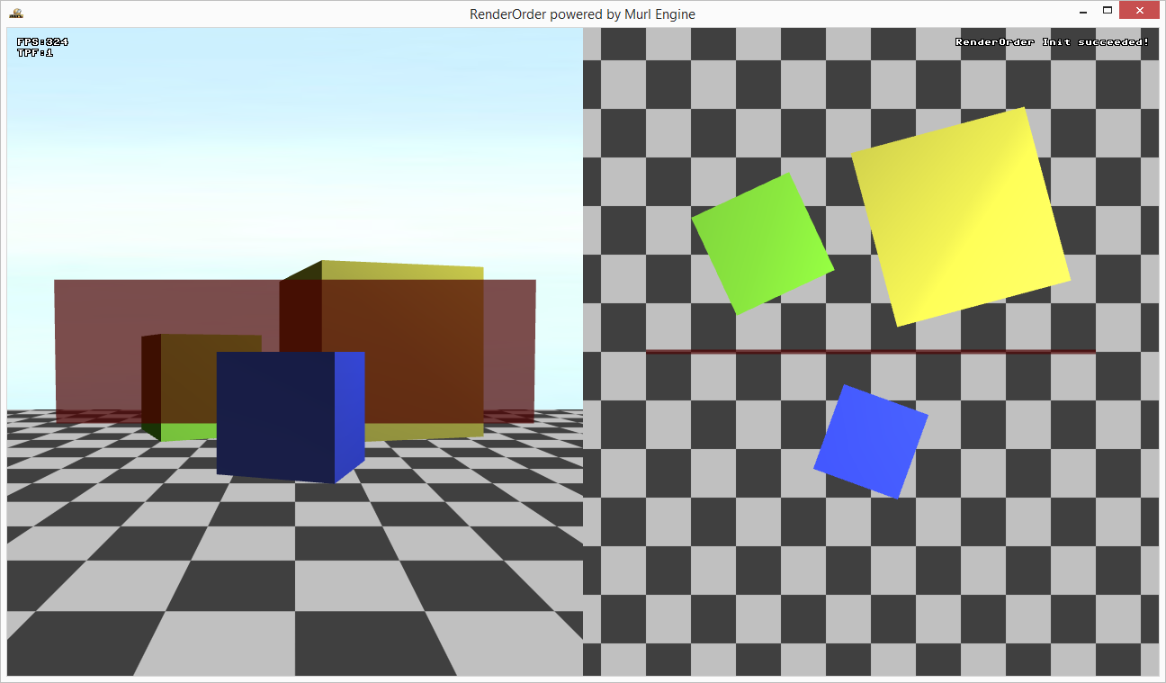
We get an image that is rendered with four cameras:
background_cameraclears the window.main_camerauses a blue image to draw the background.camera_leftrenders the scene with a perspective camera.camera_rightrenders the scene with an orthographic camera in a bird's eye view.
To get a correct render result for the opaque and transparent faces we use depthBufferMode="READ_AND_WRITE" for the opaque material and depthBufferMode="READ_ONLY" for the transparent material.