A fundamental problem in the development of applications for different devices are the different screen resolutions and different aspect ratios. In this tutorial, some possibilities how to handle these situations will be presented.
At first, we create a test program with a window size of 800x600 pixels and draw two rectangles on the Z-plane 0. The first rectangle should fill the whole screen, while the second one should cover the first and have a margin of 25 pixels on all sides.
Version 1
Depth Order
Usually, depth ordering is done through a Z-buffer. However, a manual control on object level is often preferred. This can be achieved with the parameter depthOrder.
All objects are first sorted by their Z-position and, if one value appears more than once, by their depthOrder value with the larger depthOrder value covering the smaller one. The admissible value range for the attribute depthOrder is equal to one SInt32.
In order to sort objects by their depthOrder value, the material attribute depthBufferMode has to be set to "NONE" or "READ_ONLY. The admissible values for the attribute depthBufferMode are defined in the DepthBufferMode enumeration found in the file murl_i_enums.h :
murl/base/include/engine/murl_i_enums.h
For our tutorial we define a suitable program and material, together with two parameter sets representing two different shades of blue:
        <FixedProgram
            id="prg_color"
            coloringEnabled="yes"
        />
        <Material
            id="mat_color"
            programId="prg_color"
            depthBufferMode="NONE"
        />

        <FixedParameters
            id="par_cube_color"
            diffuseColor="0f, 0.50f, 0.75f, 1f"
        />
        <FixedParameters
            id="par_background_color"
            diffuseColor="0.5f, 0.75f, 0.9f, 1f"
        />
and draw two rectangles with those colors and suitable depthOrder values:
        <ParametersState
            parametersId="/material/par_cube_color"
        />
        <PlaneGeometry
            id="rectangle"
            scaleFactorX="750"
            scaleFactorY="550"
            depthOrder="1"
            posX="0" posY="0" posZ="0"
        />

        <ParametersState
            parametersId="/material/par_background_color"
        />
        <PlaneGeometry
            id="background"
            scaleFactorX="800"
            scaleFactorY="600"
            depthOrder="0"
            posX="0" posY="0" posZ="0"
        />
In addition we draw four "hidden" squares, which are placed outside of the visible field of view:
        <PlaneGeometry
            id="hidden0"
            scaleFactor="42"
            posX="0" posY="350" posZ="0"
        />

        <PlaneGeometry
            id="hidden1"
            scaleFactor="42"
            posX="0" posY="-350" posZ="0"
        />

        <PlaneGeometry
            id="hidden2"
            scaleFactor="42"
            posX="450" posY="0" posZ="0"
        />

        <PlaneGeometry
            id="hidden3"
            scaleFactor="42"
            posX="-450" posY="0" posZ="0"
        />
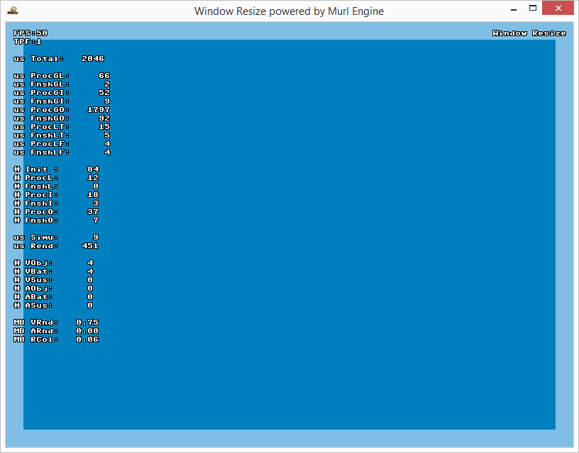
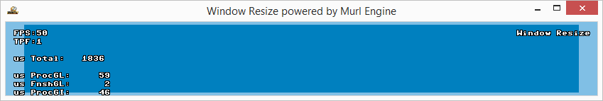
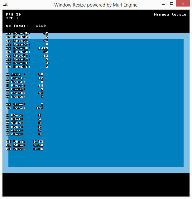
As desired, the two overlain rectangles are displayed in the window:
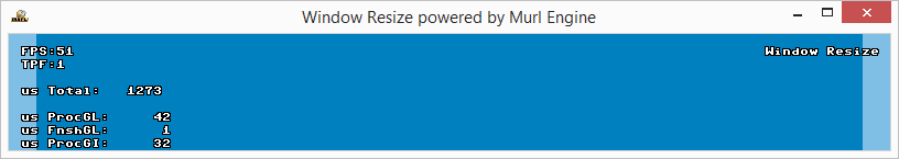
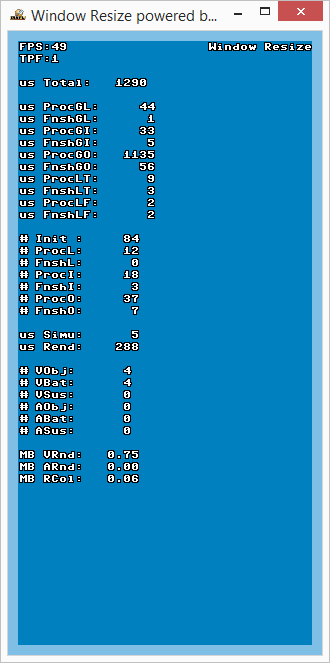
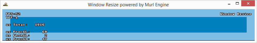
As soon as the aspect ratio changes, either hidden objects are displayed or a part of the picture is cut off:
If fieldOfViewY instead of fieldOfViewX is specified for the camera, the hidden objects on the left and right side are displayed rather than above and below the rectangles.
There is more than one solution for this problem:
- Lock Aspect Ratio
- Stretch Picture
- Fit Picture with Margin (Letterbox / Pillarbox)
- Fit Picture by Cutting (Zoom)
- Adjust Content
The sub section Screen Resolution shows additionally how to query the resolution of the primary screen .
Lock Aspect Ratio
Locking the aspect ratio can simply be done by calling the IAppConfiguration's method SetLockWindowAspectEnabled(true) in the method Configure():
Bool App::WindowSizeApp::Configure(IEngineConfiguration* engineConfig, IFileInterface* fileInterface)
{
    IAppConfiguration* appConfig = engineConfig->GetAppConfiguration();

    engineConfig->SetProductName("WindowResize");
    appConfig->SetWindowTitle("Window Resize powered by murl engine");
    appConfig->SetDisplaySurfaceSize(800, 600);
    appConfig->SetFullScreenEnabled(false);

    appConfig->SetLockWindowAspectEnabled(true);

    return true;
}
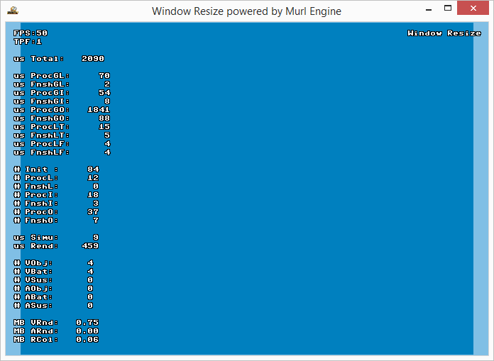
By doing so, the aspect ratio constantly remains the same and the picture is always displayed filling the window.
However, there is still a problem, if the screen has a different aspect ratio and the application is run in full screen mode. Keep in mind that applications on mobile devices are always displayed full screen. On a Windows PC it is possible to switch between window and fullscreen mode by pressing the keystroke combination ALT+ENTER.
Stretch Picture
For this method, both fieldOfViewX and fieldOfViewY have to be specified and the aspectRatio has to be set to 0 for the camera node:
        <Camera
            id="camera"
            viewId="view"
            fieldOfViewX="400"
            fieldOfViewY="300"
            aspectRatio="0"
            nearPlane="400" farPlane="2500"
            clearColorBuffer="1"
        />
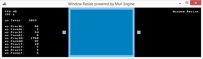
As a result, the picture is always displayed filling the whole window. It is, however, deformed:

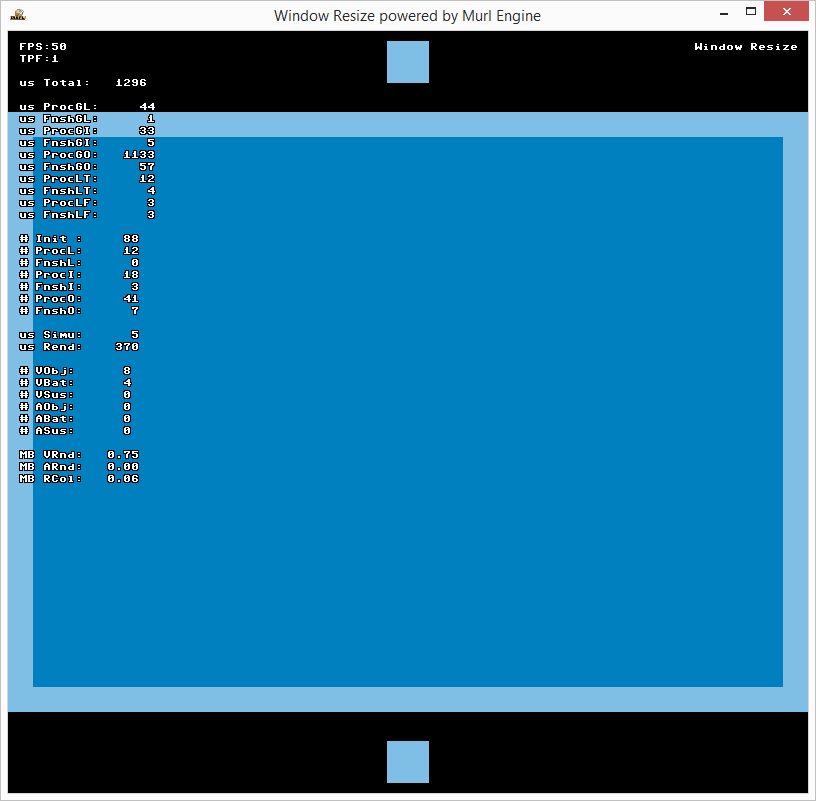
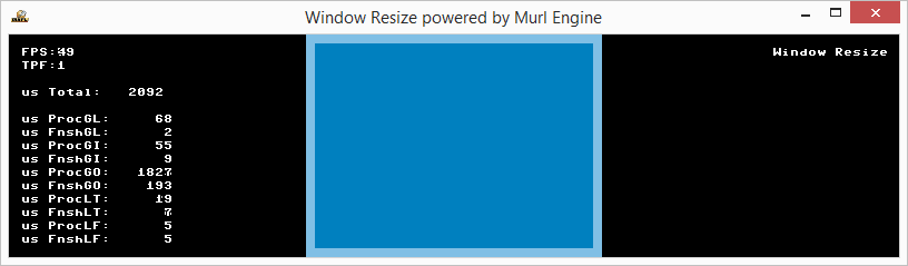
Fit Picture with Margin (Letterbox / Pillarbox)
If the picture (400x300) should be displayed without deformation the attribute aspectRatio hast to be set to 1.
The attribute enableAspectClipping of the camera node controls the fitting method: Use false to fit the picture with a margin into the window. Use true to fit the picture into the window by cutting off some parts. Per default the picture is fitted with a margin so that the whole picture is visible in any case.
        <Camera
            id="camera"
            viewId="view"
            fieldOfViewX="400"
            fieldOfViewY="300"
            aspectRatio="1"
            nearPlane="400" farPlane="2500"
            clearColorBuffer="1"
        />
In addition the attribute enableBorderMask="true" can be used to mask the picture. Doing so avoids the drawing of areas outside of the picture (with the hidden objects):
        <Camera
            id="camera"
            viewId="view"
            fieldOfViewX="400"
            fieldOfViewY="300"
            aspectRatio="1"
            enableBorderMask="true"
            nearPlane="400" farPlane="2500"
            clearColorBuffer="1"
        />
Fit Picture by Cutting (Zoom)
In order to fit the picture into the window by cutting off some parts, only the attribute enableAspectClipping of the camera node needs to be set to true.
        <Camera
            id="camera"
            viewId="view"
            fieldOfViewX="400"
            fieldOfViewY="300"
            aspectRatio="1"
            enableAspectClipping="true"
            nearPlane="400" farPlane="2500"
            clearColorBuffer="1"
        />

Adjust Content
In order to be able to adjust the content, we need to determine any changes of the window size. For this situation, the IAppConfiguration object provides the method HasDisplaySurfaceSizeChanged(). Before using this method, we need another member variable of the type ChangeInspector.
ChangeInspector mDisplaySurfaceSizeInspector;
We are now able to determine through the OnProcessTick() method, if the window size has changed, and to react accordingly.
By using the method GetAppConfiguration() on the IEngineConfiguration object retrieved from the given Logic::IState parameter we receive a pointer to the IAppConfiguration object. The object mDisplaySurfaceSizeInspector saves the frame number of the last change. The method HasDisplaySurfaceSizeChanged() now checks, if the display surface size (i.e. window size) of the current frame has changed compared to the frame with the saved frame number.
If the frame number has been changed, the new width and height can be queried by using GetDisplaySurfaceSizeX() and GetDisplaySurfaceSizeY(). The frame number in the ChangeInspector is automatically updated.
void App::WindowSizeLogic::OnProcessTick(const Logic::IState* state)
{
    Logic::IDeviceHandler* deviceHandler = state->GetDeviceHandler();

    const IAppConfiguration* appConfig = state->GetEngineConfiguration()->GetAppConfiguration();
    if (appConfig->HasDisplaySurfaceSizeChanged(mDisplaySurfaceSizeInspector))
    {
        UInt32 width = appConfig->GetDisplaySurfaceSizeX();
        UInt32 height = appConfig->GetDisplaySurfaceSizeY();
        Debug::Trace("New Screen Size %i %i", width, height);

        // Uncomment the desired adjustment method call below

        //(1) realign content
        // RealignContent(width,  height);
    }

    if (deviceHandler->WasRawKeyPressed(RAWKEY_ESCAPE) ||
        deviceHandler->WasRawButtonPressed(RAWBUTTON_BACK))
    {
        deviceHandler->TerminateApp();
    }
}
Following the same scheme, it is possible to react to any changes within the configuration, e.g. config->HasLanguageChanged() or config->HasAccelerometerActiveChanged(). For this purpose, a ChangeInspector object has to be defined for every property.
The rectangles are now modified with SetScaleFactor() in the method RealignContent:
void App::WindowSizeLogic::RealignContent(UInt32 width, UInt32 height)
{
    int h = Real(800)*height/width;
    mRectBackground->SetScaleFactorY(h);
    if (h>50)
        mRectForeground->SetScaleFactorY(h-50);
    else
        mRectForeground->SetScaleFactorY(0);
}
        //(1) realign content
        RealignContent(width,  height);
Don't forget to change back any modifications you may have made to the camera node.
<Camera
    id="camera"
    viewId="view"
    fieldOfViewX="400"
    nearPlane="400" farPlane="2500"
    clearColorBuffer="1"
/>
Screen Resolution
The resolution of the primary screen can be queried with the IAppConfiguration object and the methods GetDisplaySurfaceSizeX() and GetDisplaySurfaceSizeY() in the Configure() method.
Bool App::WindowSizeApp::Configure(IEngineConfiguration* engineConfig, IFileInterface* fileInterface)
{
    IAppConfiguration* appConfig = engineConfig->GetAppConfiguration();

    UInt32 width = appConfig->GetDisplaySurfaceSizeX();
    UInt32 height = appConfig->GetDisplaySurfaceSizeY();
    Debug::Trace("Primary Monitor Size %i x %i", width, height);

    engineConfig->SetProductName("WindowResize");
    appConfig->SetWindowTitle("Window Resize powered by murl engine");
    appConfig->SetDisplaySurfaceSize(800, 600);
    appConfig->SetFullScreenEnabled(false);

    //appConfig->SetLockWindowAspectEnabled(true);

    return true;
}
By using these values, it is possible to appropriately react e.g. in order to load different resource packages.
- Note
- In order to use the method
Debug::Trace()within the methodConfigure(), the header filemurl_debug_trace.hhas to be included in advance.
Version 2: Mask View
Using a view mask, it is possible to restrict the drawing area to a specific section of the window.
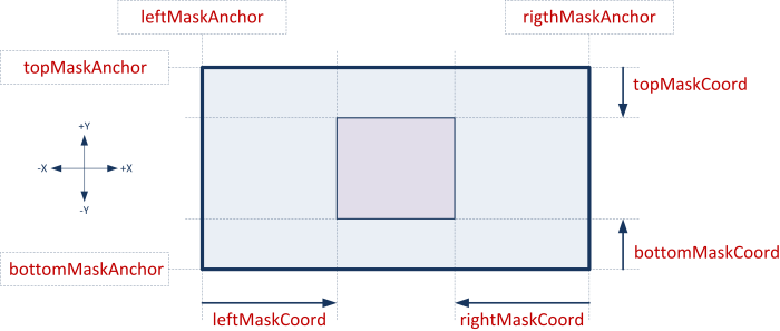
A mask can be defined for every View node by using the attributes leftMaskCoord, rightMaskCoord, topMaskCoord or bottomMaskCoord. The values are specified in pixels relative to the window border and the corresponding anchor point.
With the following specifications we create a second view which has a margin of exactly 100 pixels to the window border. As the new view has a larger depthOrder, it is located in front of the existing one. In order not to clear the contents previously rendered by the first view, we specify "no" for the clearColorBuffer attribute, as for performance reasons a clear operation always clears the entire output surface.
    <View
        id="view2"
        depthOrder="1"
        leftMaskCoord="100"
        rightMaskCoord="-100"
        topMaskCoord="-100"
        bottomMaskCoord="100"
    />

    <Camera
        id="test_camera"
        viewId="view2"
        fieldOfViewX="400"
        nearPlane="400" farPlane="2500"
        clearColorBuffer="no"
    />
    <CameraTransform
        cameraId="test_camera"
        posX="0" posY="0" posZ="800"
    />
    <CameraState
        cameraId="test_camera"
    />
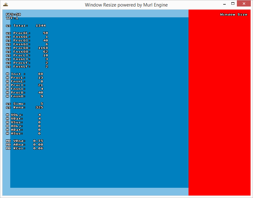
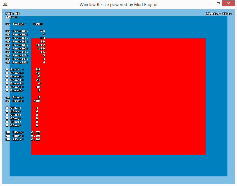
Within that new view we place another full-screen plane (800x600 units) in red.
    <MaterialState
        materialId="/material/mat_color"
        slot="0"
    />

    <ParametersState
        parametersId="/material/par_overlay_color"
    />
    <PlaneGeometry
        id="background"
        scaleFactorX="800"
        scaleFactorY="600"
        depthOrder="0"
        posX="0" posY="0" posZ="0"
    />
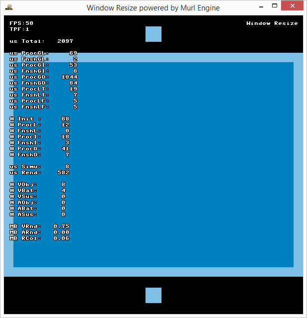
The margin of the second view is always 100 pixels, even if the window size changes. We can now see that this new full-screen plane is actually clipped along that margin:
Mask Anchors
It is also possible to set anchor points to the opposite window border. By doing so, a view can e.g. be docked to any border. The attributes are leftMaskAnchor and rightMaskAnchor with the possible values "LEFT", "RIGHT" and "CENTER", and topMaskAnchor and bottomMaskAnchor with possible values "TOP", "BOTTOM" and "CENTER". See the IEnums::AlignmentX and IEnums::AlignmentY enumerations for details.
In order to dock e.g. the second view with a constant width of 200 pixels to the right border, it is sufficient to set the left anchor to "RIGHT" and to set the left mask by 200 pixels to the left (i.e. -200).
<View id="view2"
    depthOrder="1"
    leftMaskAnchor="RIGHT"
    leftMaskCoord="-200"
/>