In order to convert graphics into a format suitable for textures, the atlas_generator is provided.
The atlas_generator positions all graphics into a texture graphic and creates the corresponding graphic information.
For our tutorial we have downloaded some graphics from https://opengameart.org. Their original address is indicated in the file data/orig/AUTHOR.txt.
data/orig/back_1.pngdata/orig/nightraiderfixed.pngdata/orig/warrior1_0.pngdata/orig/warrior2_0.pngdata/orig/sz/2k_anim1.pngdata/orig/sz/2k_anim2.pngdata/orig/sz/2k_anim3.pngdata/orig/sz/2k_anim4.png
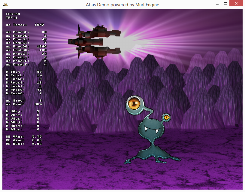
We have a background image, three spaceships and a directory with four single-images of an alien animation.
For the alien animation we create a texture as well as the corresponding <Rectange> resources and for the background and the spaceships a texture as well as the corresponding <PlaneGeometry> nodes.
The atlas_generator reads the configuration from XML files.
scripts/atlas_config_alien.xmlscripts/atlas_config_misc.xml
Every task has its own configuration file.
<?xml version="1.0"?>
<!-- Copyright 2013 Spraylight GmbH -->

<AtlasGenerator xmlns="https://murlengine.com">

    <Input path="../orig/sz">

        <Crop cropThreshold="8i" cropCenterX="10" cropCenterY="0"/>

        <Matte color="0i, 0i, 0i"/>

        <Image scanAll="yes"/>

    </Input>

    <Output path="../packages/main.murlres">

        <Atlas sizeRaster="2"/>

        <Image name="gfx_alien.png" margin="1"/>

        <AtlasXML name="atlas_alien.xml"/>

    </Output>
</AtlasGenerator>
Within this file we create the texture for the alien animation.
The atlas_generator always needs an <AtlasGenerator> root tag section with one or more <Input> tag sections and one <Output> tag section.
The <Input> tag can specify a path for all input files with the attribute path="../orig/sz". In our tutorial all paths are specified in relation to the scripts directory. From this point, the atlas_generator is started via shell script.
The <Image scanAll="yes"/> determines the input image file and the attribute scanAll="yes" reads all files within the path of the input files. Directories or files with a preceding dot are ignored. This means that in our tutorial all four 2k_anim… images are loaded.
The <Matte color="0i, 0i, 0i"/> tag defines the color of the pixel with an alpha value of 0. Several popular graphic programs save random RGB color values in pixels with an alpha value of 0. If pixels are interpolated (e.g. in 3D graphic chips), this causes wrong-colored margins in such sections. In order to solve this issue, this directive precautionarily replaces all pixels with an alpha value of 0 with the RGB values of the color="0i, 0i, 0i" attribute.
The <Crop cropThreshold="8i" cropCenterX="10" cropCenterY="0"/> allows cutting empty margins of large images. By doing so, the required space on the texture can be considerably reduced.
Our alien graphic is a very tricky example. It has almost "invisible" alpha gradients (alpha 0–15) which are saved in the margins. Furthermore, the figure is located in the middle of a too large image.
All margins with an alpha value of 8 or less are removed with the attribute cropThreshold="8i".
As this is an image sequence, it is very important that all images are and remain congruent to each other. This can be done by using the attribute cropCenter="0" which ensures that all margins are cut equally. Since the object is not located in the middle of the image, its center is moved with the attributes cropCenterX="10" and cropCenterY="0".
The <Output> tag can specify a path for all output files with the attribute path="../packages/main.murlres". In our tutorial all paths are specified in relation to the scripts directory. From this point, the atlas_generator is started via shell script.
The <Atlas sizeRaster="2"/> tag specifies the properties of the texture. The attribute sizeRaster="2" determines the raster of the images to embed. In our case, all dimensions of the single-images can be divided by 2. During this process, the single-pictures are not modified, but positioned in the center of the raster. The advantage is that all images are always placed on whole-numbered pixels on the screen.
If an image with a width of e.g. 17 pixels is placed on position (0/0) on the screen, it will be displayed blurrily because the graphic chip on the right and left side of the coordinate renders 8.5 pixels interpolated. Admittedly, this can be avoided by moving the coordinate to e.g. (0.5/0). However, if many different graphics are used, this option may result in a rather confusing code.
Using a raster is much simpler since the dimensions of the graphics do not have to be considered as long as they are displayed on whole-numbered coordinates.
Basically, animated images will be displayed on calculated non-whole-numbered coordinates as well. In this case, the blurring cannot be avoided, but it will not affect the appearance of the graphic. Static images, however, e.g. in menus, will very well leave a blurred impression.
The term "whole-numbered coordinate" refers to the camera setting which is specified for a 1:1 image of the virtual coordinate system for screen output.
The <Image name="gfx_alien.png" margin="1"/> tag indicates the name of the texture image file. Additionally, a margin of 1 pixel for all input images is specified with the attribute margin="1". This additional margin is necessary in order avoid using pixels of adjacent graphics. The margin is filled with the color of the corresponding matte attribute. If the color of the matte attribute has not been defined, the margin remains unaffected.
The <AtlasXML name="atlas_alien.xml"/> tag indicates the name of the XML file, which the texture coordinates in form of an atlas resource are specified in.
<?xml version="1.0"?>
<!-- Copyright 2013 Spraylight GmbH -->

<AtlasGenerator xmlns="https://murlengine.com">

    <Input path="../orig">

        <Matte color="0i, 0i, 0i"/>

        <Image name="back_1.png" sizeX="800" sizeY="640"/>
        <Image name="nightraiderfixed.png"/>
        <Image name="warrior1_0.png"/>
        <Image name="warrior2_0.png"/>

    </Input>

    <Output path="../packages/main.murlres">

        <Atlas sizeRaster="2"/>

        <Image name="gfx_misc.png" margin="1"/>

        <PlaneGraphXML name="planes_misc.xml"/>

    </Output>

</AtlasGenerator>
Here, the texture for the background and the spaceship images are created. All input image files are clearly specified with an <Image name="..."/> tag.
Additionally, the <Image name="back_1.png" sizeX="800" sizeY="640"/> tag defines the pixel size of the image file in the output texture.
In our tutorial the screen has a size of 800x600 pixels. The background image, however, is larger and therefore scaled accordingly. The height of 640 pixels is intended in order to keep the aspect ratio of the image. The top and bottom side will each be displayed by 20 pixels less. Generally, it is recommended to use the atlas_generator only for quickly created prototypes. In order to ensure best possible image quality, all graphics should be prepared from scratch.
The <PlaneGraphXML name="planes_misc.xml"/> tag indicates the name of the XML file, which the texture coordinates in form of an atlas resource are specified in.
A full description of all tags and attributes can be found in the tools documentation.
The following script files (Unix/Windows) contain the calls which direct the atlas_generator to create the textures and metadata.
scripts/atlas_generator.shscripts/atlas_generator.cmd
When the script file is called, the following files are created:
data/packages/main.murlres/atlas_alien.xmldata/packages/main.murlres/gfx_alien.pngdata/packages/main.murlres/gfx_misc.pngdata/packages/main.murlres/planes_misc.xml
The created files can directly be used in the graph node.
Scene Graph
As a first step, the created resources have to be added to the package.
<?xml version="1.0" ?>
<!-- Copyright 2013 Spraylight GmbH -->
<Package id="package_main">

    <!-- Animation resources -->
    <Resource id="anim_alien"       fileName="anim_alien.xml"/>

    <!-- Atlas resources -->
    <Resource id="atlas_alien"      fileName="atlas_alien.xml"/>

    <!-- Bitmap resources -->
    <Resource id="gfx_alien"        fileName="gfx_alien.png"/>
    <Resource id="gfx_misc"         fileName="gfx_misc.png"/>
    <Resource id="planes_misc"      fileName="planes_misc.xml"/>

    <!-- Graph resources -->
    <Resource id="graph_main"       fileName="graph_main.xml"/>
    <Resource id="graph_materials"  fileName="graph_materials.xml"/>
    <Resource id="graph_textures"   fileName="graph_textures.xml"/>

    <!-- Graph instances -->
    <Instance graphResourceId="graph_materials"/>
    <Instance graphResourceId="graph_textures"/>
    <Instance graphResourceId="graph_main"/>

</Package>
Texture Definition
In order to use textures more than once, nodes are recommended for referencing.
<?xml version="1.0" ?>
<!-- Copyright 2013 Spraylight GmbH -->
<Graph>
    <Namespace id="textures" activeAndVisible="no">

        <FlatTexture id="tex_alien"
        imageResourceId="package_main:gfx_alien"
        pixelFormat="R8_G8_B8_A8"
        useMipMaps="no"/>

        <Instance graphResourceId="package_main:planes_misc"/>
        <FlatTexture id="tex_misc"
        imageResourceId="package_main:gfx_misc"
        pixelFormat="R8_G8_B8_A8"
        useMipMaps="no"/>

    </Namespace>
</Graph>
Here, it has to be considered that the <PlaneGeomentry> nodes created by the atlas_generator are instantiated via <Instance graphResourceId="package_main:planes_misc"/>.
Main Graph
<?xml version="1.0" ?>
<!-- Copyright 2013 Spraylight GmbH -->
<Graph>
    <Namespace id="main">

        <View id="view"/>

        <Camera id="camera"
        viewId="view"
        fieldOfViewX="400"
        nearPlane="400" farPlane="2500"
        clearColorBuffer="yes"/>
        <CameraTransform cameraId="camera"
        posX="0" posY="0" posZ="800"/>
        <CameraState cameraId="camera"/>

        <FixedParameters id="screen_parameters"/>
        <ParametersState parametersId="screen_parameters"/>

        <Reference targetId="/materials/state_plain_tex_color"/>

        <TextureState textureId="/textures/tex_misc"/>
        <Reference targetId="/textures/back_1"/>

        <Transform id="ship_position" depthOrder="2">
            <Scale id="ship_scale">
                <Switch id="ship_switch">
                    <Reference targetId="/textures/nightraiderfixed"/>
                    <Reference targetId="/textures/warrior1_0"/>
                    <Reference targetId="/textures/warrior2_0"/>
                </Switch>
            </Scale>
        </Transform>

        <Timeline id="alien_timeline" startOnActivate="yes"
            startTime="0.0" endTime="3.0" numberOfLoops="-1">
            <TextureState textureId="/textures/tex_alien"/>
            <PlaneSequenceGeometry atlasResourceId="package_main:atlas_alien"
            posX="100" posY="-100" depthOrder="1"
            controller.animationResourceId="package_main:anim_alien"
            controller.animationKeys="INDEX"/>
        </Timeline>

    </Namespace>
</Graph>
In order to display the graphics of the created texture, the corresponding texture state <TextureState textureId="/textures/tex_misc"/> is set as a first step.
Afterwards, the background is displayed by referencing the created <PlaneGeometry> via <Reference targetId="/textures/back_1"/>.
In the next block a <Transform> node to animate the spaceships, a <Scale> node to resize and a <Switch> node to select a certain spaceship are located.
The <Switch> node has an index as property, which activates the child node with the corresponding index (activeAndVisible="true") and deactivates all others (activeAndVisible="false"). If the index is invalid, all child nodes are deactivated. The default index is "-1", which is always an invalid index and therefore deactivates all child nodes. In our tutorial, the valid index range is 0-2 which is specified in the code below.
Finally, the alien is animated in the last block. The <Timeline> node is configured to the effect that the animation automatically starts and continues to infinity. In order to display the graphics of the alien, the corresponding texture state <TextureState textureId="/textures/tex_alien"/> is set. The <PlaneSequenceGeometry atlasResourceId="package_main:atlas_alien"> node uses the created atlas resource.
Application
The atlas demo application implements a simple animation to randomly move the spaceships.
Logic Setup
        class AtlasDemoLogic : public Logic::BaseProcessor
        {
        public:
            AtlasDemoLogic(Logic::IFactory* factory);
            virtual ~AtlasDemoLogic();

        protected:
            virtual Bool OnInit(const Logic::IState* state);
            virtual Bool OnDeInit(const Logic::IState* state);
            virtual void OnProcessTick(const Logic::IState* state);

            Logic::TransformNode mShipPosition;
            Logic::ScaleNode mShipScale;
            Logic::SwitchNode mShipSwitch;

            Util::TT800 mRng;
            Logic::AnimationVector mShipAnimation;
        };
In order to create random numbers, we instantiate a RandomNumberGenerator (RNG) – in our tutorial the Util::TT800 class. More RNG classes can be found in the header murl_util_rng.h.
To programmatically control an animation, the animation resources, such as those for the alien animation, are not sufficient since these cannot be modified anymore during program execution. For this purpose, animation classes are provided for the logic implementation, which can be modified during program execution.
In our tutorial, we need a vector animation for the spaceship position, which is instantiated with Logic::AnimationVector mShipAnimation.
Logic Initialization
Bool App::AtlasDemoLogic::OnInit(const Logic::IState* state)
{
    Graph::IRoot* root = state->GetGraphRoot();

    AddGraphNode(mShipPosition.GetReference(root, "/main/ship_position"));
    AddGraphNode(mShipScale.GetReference(root, "/main/ship_scale"));
    AddGraphNode(mShipSwitch.GetReference(root, "/main/ship_switch"));

    mShipAnimation.AddKey(Real(0.0), Vector(-600, 0, 0, 1), IEnums::INTERPOLATION_LINEAR);
    mShipAnimation.AddKey(Real(1.0), Vector( 600, 0, 0, 1));
    AddStepable(mShipAnimation);

    return true;
}
As a first step, references to the spaceship nodes are created and added to the processor base class.
Logic Animation
Basically, the logic animation works exactly as the graph timeline node and graph animation resources. Any number of data points, so-called keys, can be specified. In our tutorial, two keys for the starting point and endpoint of the spaceship position are specified with mShipAnimation.AddKey(...).
The first parameter indicates the time of the data point, the second parameter the value of the data point and the third parameter optionally the interpolation function (the default value is the linear interpolation).
The object to be animated is a template class and can basically work with every data type, if it has the operators for addition, subtraction and multiplication correctly implemented.
For the following data types pre-defined animation types are available:
AnimationVectorAnimation with data points of vector classesAnimationColorAnimation with data points of color classesAnimationRealAnimation with data points of real data type classesAnimationUInt32Animation with data points of UInt32 data type classesAnimationSInt32Animation with data points of SInt32 classes
Stepable Objects
Objects implementing the Logic::IStepable interface are called stepables. Stepable objects are light-weight objects which need a time or frame information. As the processor class, stepable objects have an OnProcessTick() method processing each logic step. This is automatically done by the processor base class with the method AddStepable() as soon as a stepable object instance is added since the processor class has a built-in StepableObserver.
In our tutorial, we use a Logic::AnimationVector instance, which implements the corresponding OnProcessTick() method for time-based calculation. Therefore, it is necessary to add this instance with AddStepable(mShipAnimation).
Logic Processing
void App::AtlasDemoLogic::OnProcessTick(const Logic::IState* state)
{
    if (!mShipAnimation.IsOrWasRunning())
    {
        SInt32 shipIndex = mRng.RandUInt(0, 2);
        mShipSwitch->SetIndex(shipIndex);

        Real scaleFactor = mRng.RandReal(Real(0.5), Real(1.0));
        mShipScale->SetScaleFactor(scaleFactor);

        Real shipPositionY = mRng.RandReal(Real(100), Real(200));
        mShipAnimation.mKeys[0].mValue.y = shipPositionY;

        Real flightDuration = mRng.RandReal(Real(1.5), Real(3.5));
        mShipAnimation.mKeys[1].mTime = flightDuration;
        shipPositionY = mRng.RandReal(Real(100), Real(200));
        mShipAnimation.mKeys[1].mValue.y = shipPositionY;

        mShipAnimation.StartForward();
    }

    mShipPosition->SetPosition(mShipAnimation.GetCurrentValue());
}
As a first step, we check, if the spaceship animation runs straightly. If not, random animation parameters are specified for the spaceship movement:
- Firstly, an index is determined with the RNG in order to activate one of the three spaceships.
- Afterwards, a scale factor is determined with the RNG to vary the size of the spaceship.
- Finally, the vertical starting and end position as well as the flight duration are defined randomly.
The animation keys are manipulated by accessing the mKeys array. Every key element has the time in mTime, the value in mValue and the interpolation function in mInterpolation. As a last step, the animation is started with mShipAnimation.StartForward().
While the animation is playing, it is not allowed to add or remove data points with the array mKeys. Apart from that, it is possible at any time.
At the end of the method, the current position value of the spaceship animation is transferred to the graph node for every logic step. Therefore, the spaceship is in motion.