In the first 3d tutorial we show how to create a very simple 3d scene surrounded by a skybox and how to move the camera in the scene.
Skybox
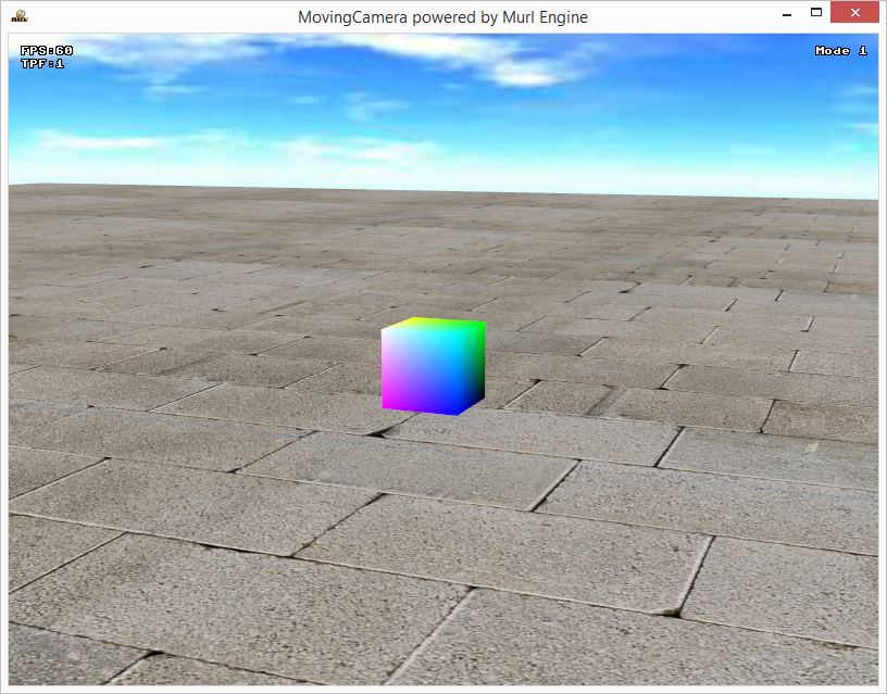
To keep the example easy, we create a simple scene with merely a cube on a plane. Additionally we enclose the scene with a skybox.
A skybox is a popular technique to create a background for a 3d scene. The whole scene is wrapped inside a textured cuboid. Each plane of the cuboid is textured with a different image (cube mapping). Beside the sky, the skybox textures may also contain distant mountains or buildings, thus making the scene look bigger and more impressive.
- Note
- We will use the cube mapping technique not only for the skybox but also for the cube.
CubemapTexture
The node Graph::CubemapTexture can be used to create a texture object which contains all six texture images for the cuboid.
Firstly we specify the individual image resources in the file package.xml.
    <!-- Image resources -->
    <Resource id="gfx_plane"          fileName="plane.png"/>
    <Resource id="gfx_cube_nx"        fileName="cube_neg_x.png"/>
    <Resource id="gfx_cube_px"        fileName="cube_pos_x.png"/>
    <Resource id="gfx_cube_ny"        fileName="cube_neg_y.png"/>
    <Resource id="gfx_cube_py"        fileName="cube_pos_y.png"/>
    <Resource id="gfx_cube_nz"        fileName="cube_neg_z.png"/>
    <Resource id="gfx_cube_pz"        fileName="cube_pos_z.png"/>
    <Resource id="gfx_sky_up"         fileName="sky1_up.jpg"/>
    <Resource id="gfx_sky_down"       fileName="sky1_down.jpg"/>
    <Resource id="gfx_sky_left"       fileName="sky1_left.jpg"/>
    <Resource id="gfx_sky_right"      fileName="sky1_right.jpg"/>
    <Resource id="gfx_sky_front"      fileName="sky1_front.jpg"/>
    <Resource id="gfx_sky_back"       fileName="sky1_back.jpg"/>
Next we create a CubemapTexture object and define a suitable textureSlot with a TextureState node.
    <FlatTexture id="texture_plane" imageResourceId="gfx_plane"/>

    <CubemapTexture id="texture_cube"
                    imageResourceIdPosX="gfx_cube_nx" imageResourceIdNegX="gfx_cube_px"
                    imageResourceIdPosY="gfx_cube_ny" imageResourceIdNegY="gfx_cube_py"
                    imageResourceIdPosZ="gfx_cube_nz" imageResourceIdNegZ="gfx_cube_pz"
                    wrapModeX="CLAMP_TO_EDGE"
                    wrapModeY="CLAMP_TO_EDGE"
    />

    <CubemapTexture id="texture_sky"
                    imageResourceIdPosX="gfx_sky_right" imageResourceIdNegX="gfx_sky_left"
                    imageResourceIdPosY="gfx_sky_up"    imageResourceIdNegY="gfx_sky_down"
                    imageResourceIdPosZ="gfx_sky_front" imageResourceIdNegZ="gfx_sky_back"
                    wrapModeX="CLAMP_TO_EDGE"
                    wrapModeY="CLAMP_TO_EDGE"
    />

    <TextureState slot="0" textureId="texture_plane"/>
    <TextureState slot="2" textureId="texture_cube"/>
    <TextureState slot="3" textureId="texture_sky"/>
Changing the attribute wrapModeX and wrapModeY from default value REPEAT to CLAMP_TO_EDGE prevents unaesthetic artifacts on the edges.
Shader
As there is no FixedProgram which can be used to draw cube maps, we need a ShaderProgram.
For this, we first need to define the shader code as XML shader resource in the file shader_skybox.xml:
<?xml version="1.0" ?>

<Shader languages="GLSL_ES_120,HLSL_30,HLSL_40_93">

    <Attributes>
        <Attribute item="COORD" type="FLOAT_VECTOR_4"/>
    </Attributes>

    <ConstantBuffers>
        <ConstantBuffer item="MODEL"/>
        <ConstantBuffer item="CAMERA"/>
    </ConstantBuffers>

    <Varyings>
        <Varying name="vCubeCoord" type="FLOAT_VECTOR_3" precision="MEDIUM"/>
    </Varyings>

    <Textures>
        <Texture unit="0" type="CUBE" precision="LOW"/>
    </Textures>

    <VertexSource>
        <![CDATA[
            void main()
            {
                gl_Position = uCameraViewProjectionMatrix * (uModelMatrix * aPosition);
                vCubeCoord = aPosition.xyz;
            }
        ]]>
    </VertexSource>

    <FragmentSource>
        <![CDATA[
            void main()
            {
                gl_FragColor = textureCube(uTexture0, vCubeCoord);
            }
        ]]>
    </FragmentSource>

</Shader>
The new file needs to be listed as a resource in the package.xml file before it can be used.
    <!-- Shader resources -->
    <Resource id="shader_skybox_res"  fileName="shader_skybox.xml"/>
Next, we define a Shader node and a ShaderProgram node in the materials.xml file.
<Shader id="shader_skybox"
    shaderResourceId="shader_skybox_res"
/>
<ShaderProgram
    id="prg_cube"
    vertexShaderId="shader_skybox"
    fragmentShaderId="shader_skybox"
/>
The ShaderProgram can then be used to create the Material nodes.
<Material
    id="mat_cube"
    visibleFaces="FRONT_AND_BACK"
    programId="prg_cube"
/>
<Material
    id="mat_sky"
    visibleFaces="BACK_ONLY"
    programId="prg_cube"
/>
Now we are able to define the nodes for the skybox, the cube and the plane.
<MaterialState slot="11" materialId="/material/mat_cube"/>
<MaterialState slot="12" materialId="/material/mat_sky"/>

<PlaneGeometry id="plane" materialSlot="3" scaleFactor="10000" posX="0" posY="-75" angleX="90deg" texCoordX2="8" texCoordY2="8"/>
<CubeGeometry  id="cube" materialSlot="11" textureSlot="2" scaleFactor="100" posY="-25"/>
<CubeGeometry  id="skybox" materialSlot="12" textureSlot="3" scaleFactor="10000" />
Moving Camera
We define the position of the camera (as for every other object) by a number of transformations. The primary position is defined by the CameraTransform node. Additional transform operations can be defined by nesting the CameraTransform node within additional Transform nodes.
In computer graphics a transformation is usually done by multiplying the vertex data with a four-dimensional transformation matrix (see also https://en.wikipedia.org/wiki/Transformation_matrix). Each Transform node contains such a 4x4 transformation matrix.
We will move the camera by directly manipulating the transformation matrix of the CameraTransform node. When doing so, we have to keep the order of the operations in mind:
Within one Transform node the transformation order is:
- Scale
- Rotate
- Translate
The rotation order of the Euler angles within one Transform node is:
- Z
- Y
- X
The execution order for nested Transform nodes is from inner to outer. So the transformation of the most inner Transform node is applied first.
There are, of course, various possibilities for the implementation of the camera movement. Three different methods are outlined below.
Initialize
In the header file we define a reference to the CameraTransform node, two member variables to store the rotation and the position vector and an additional member variable to store the current mode.
    Murl::Logic::TransformNode mCameraTransform;
    Vector mRot;
    Vector mPos;
    UInt32 mMode;
The variables will be initialized in the constructor and in the OnInit method:
App::MovingCameraLogic::MovingCameraLogic(Logic::IFactory* factory)
: BaseProcessor(factory)
, mRot(Vector::ZERO_POSITION)
, mPos(Vector::ZERO_POSITION)
, mMode(1)
{
}
Bool App::MovingCameraLogic::OnInit(const Logic::IState* state)
{
    state->GetLoader()->UnloadPackage("startup");

    Graph::IRoot* root = state->GetGraphRoot();
    AddGraphNode(mCameraTransform.GetReference(root, "main_camera_transform"));

    if (!AreGraphNodesValid())
    {
        return false;
    }

    mPos = mCameraTransform->GetPosition();
    state->SetUserDebugMessage("Mode "+Util::UInt32ToString(mMode));
    return true;
}
Now we are able to change the position of the camera in the OnProcessTick method by altering the mCameraTransform values. We use the keyboard to control the camera:
    // get translation key input
    moveLeft     = deviceHandler->IsRawKeyPressed(RAWKEY_LEFT_ARROW);
    moveRight    = deviceHandler->IsRawKeyPressed(RAWKEY_RIGHT_ARROW);
    moveForward  = deviceHandler->IsRawKeyPressed(RAWKEY_UP_ARROW);
    moveBackward = deviceHandler->IsRawKeyPressed(RAWKEY_DOWN_ARROW);
    moveUp       = deviceHandler->IsRawKeyPressed(RAWKEY_LEFT_SHIFT);
    moveDown     = deviceHandler->IsRawKeyPressed(RAWKEY_LEFT_CONTROL);

    // get rotation key input
    if (deviceHandler->IsRawKeyPressed(RAWKEY_Q))
        rotDiffX = 1;
    else if (deviceHandler->IsRawKeyPressed(RAWKEY_A))
        rotDiffX = -1;

    if (deviceHandler->IsRawKeyPressed(RAWKEY_W))
        rotDiffY = 1;
    else if (deviceHandler->IsRawKeyPressed(RAWKEY_S))
        rotDiffY = -1;

    if (deviceHandler->IsRawKeyPressed(RAWKEY_E))
        rotDiffZ = 1;
    else if (deviceHandler->IsRawKeyPressed(RAWKEY_D))
        rotDiffZ = -1;
Reset
To reset the positon of the camera, we create an identity matrix and adjust the translation values to the initial camera position (0/0/512). The method SetTransform() is then used to overwrite the values of the transformation matrix of the CameraTransform node.
    // RESET
    if (deviceHandler->WasRawKeyPressed(RAWKEY_R))
    {
        mPos.x = 0;
        mPos.y = 0;
        mPos.z = 512;
        mRot = Vector::ZERO_POSITION;
        Matrix transformMatrix(Matrix::IDENTITY);
        transformMatrix.SetTranslationComponent(mPos);
        mCameraTransform->SetTransform(transformMatrix);
    }
Mode 1
This method directly sets the rotation and translation parameter of the transformation matrix. The rotation values are set as Euler angles (see also en.wikipedia.org/wiki/Euler_angles).
At first we calculate a direction vector depending on the currently pressed keys. This direction vector will also be used by the other methods.
The member variable mPos and mRot are used to store the current translation and rotation vector, respectively. We use the method GetTransform() to get the transformation matrix and use the methods SetRotationComponent and SetTranslationComponent to update the rotation values and translation values, respectively.
    // calculate translation vector
    Vector direction(Vector::ZERO_DIRECTION);
    if (moveForward)
        direction.z = -walkingSpeed;
    else if (moveBackward)
        direction.z =  walkingSpeed;
    if (moveLeft)
        direction.x = -walkingSpeed;
    else if (moveRight)
        direction.x =  walkingSpeed;
    if (moveUp)
        direction.y =  walkingSpeed;
    else if (moveDown)
        direction.y = -walkingSpeed;

    if (mMode == 1)
    {
        // directly set rotation parameter
        mRot.x += rotDiffX * rotSpeed;
        mRot.y += rotDiffY * rotSpeed;
        mRot.z += rotDiffZ * rotSpeed;
        mCameraTransform->GetTransform().SetRotationComponent(mRot.x, mRot.y, mRot.z);

        // move along the x/y/z axis
        mPos += direction;
        mCameraTransform->GetTransform().SetTranslationComponent(mPos);
    }
There are some disadvantages associated with this method:
- The camera moves always along the x/y/z axis of the world and not along the viewing direction.
- Due to the rotation order z, y, x, it is not possible to control the rotation independently e.g. if your viewing direction is along the x axis, it is not possible to roll. Changing the values for x and z would have the same affect (see also en.wikipedia.org/wiki/Gimbal_lock).
The best way to understand the limitations is to try it out and experiment.
- Note
- Hint! It is also possible to set the rotation by using the method
SetRotationComponentAxisAngleor by using quaternions.
Mode 2
This method solves the previous problems. We don't store and set the rotation and translation components of the matrix but instead directly apply every change by a matrix multiplication.
    if (mMode == 2)
    {
        // multiply by rotation/translation matrix
        Matrix transformMatrix(Matrix::IDENTITY);
        transformMatrix.SetRotationComponent(rotDiffX*rotSpeed, rotDiffY*rotSpeed, rotDiffZ*rotSpeed);
        transformMatrix.SetTranslationComponent(direction);
        mCameraTransform->SetTransform(mCameraTransform->GetTransform() * transformMatrix);
    }
The camera moves always along the viewing direction and you can control the roll, pitch and yaw angle independently. You can fly around.
Mode 3
The third method demonstrates a FPS style mode. For this mode we allow to control the rotation with the mouse but move always on the plane.
    if (mMode == 3)
    {
        //get rotation mouse input
        if (deviceHandler->IsRawMouseAvailable())
        {
            deviceHandler->GetRawMouseDelta(rotDiffY, rotDiffX);
            Real dummy;
            deviceHandler->GetRawWheelDelta(dummy, rotDiffZ);
            rotDiffY *= -1.0;
        }

        // FPS mode
        mRot.x += rotDiffX * rotSpeed;
        mRot.y += rotDiffY * rotSpeed;
        mRot.z += rotDiffZ * rotSpeed;
        mCameraTransform->GetTransform().SetRotationComponent(mRot.x, mRot.y, 0);

        Matrix directionTransform(Matrix::IDENTITY);
        directionTransform.SetRotationComponent(0.0, mRot.y, 0.0);
        mPos += directionTransform.Multiply(direction);
        mPos.y = 0;
        mCameraTransform->GetTransform().SetTranslationComponent(mPos);
    }
The camera moves always along the viewing direction but the y position stays always the same (or would typically be defined by the terrain). You can walk around and look up and down.